
PRESTIGE 650H - Modem/Routeur ZYXEL - Notice d'utilisation et mode d'emploi gratuit
Retrouvez gratuitement la notice de l'appareil PRESTIGE 650H ZYXEL au format PDF.

| Type de produit | Modem/Routeur ADSL |
| Marque | ZYXEL |
| Modèle | PRESTIGE 650H |
| Normes ADSL | ANSI T1.413, G.dmt, G.lite |
| Débit descendant max | 8 Mbit/s |
| Débit montant max | 832 Kbit/s |
| Interfaces LAN | 4 ports Ethernet 10/100 auto-négociation |
| Interface WAN | 1 port ADSL (RJ-11) |
| Connectivité sans fil | Optionnelle via emplacement PCMCIA (non inclus) |
| Protocoles supportés | PPP over Ethernet (PPPoE), PPP over ATM (PPPoA), RFC 1483, ENET ENCAP |
| Fonctions réseau | NAT, DHCP serveur/client, IP Alias, routage IP statique, filtrage |
| Sécurité | WEP (64/128 bits), IEEE 802.1x, filtrage MAC, pare-feu par filtres |
| Gestion | Interface Web (HTTP), Telnet, SMT (terminal), SNMP, console série |
| Alimentation | Adaptateur secteur 12 V CC, 1,25 A (max. 15 W) |
| Consommation électrique | 12 W (max.) |
| Température de fonctionnement | 0 °C à 40 °C |
| Humidité de fonctionnement | 20 % à 80 % HR (sans condensation) |
| Dimensions (L × P × H) | Environ 220 × 140 × 30 mm |
| Poids | Environ 300 g |
| Entretien et nettoyage | Débrancher l'appareil avant nettoyage. Utiliser un chiffon doux et sec. Ne pas utiliser de produits abrasifs ou de solvants. |
| Pièces détachées et réparabilité | Ce produit ne contient pas de pièces réparables par l'utilisateur. En cas de dysfonctionnement, contacter le support technique ZyXEL ou un centre agréé. |
| Informations générales | Notice complète disponible en téléchargement (368 pages). Garantie constructeur 2 ans. Fabriqué par ZyXEL Communications Corp., Taiwan. |
FOIRE AUX QUESTIONS - PRESTIGE 650H ZYXEL
Questions des utilisateurs sur PRESTIGE 650H ZYXEL
0 question sur cet appareil. Repondez a celles que vous connaissez ou posez la votre.
Poser une nouvelle question sur cet appareil
Téléchargez la notice de votre Modem/Routeur au format PDF gratuitement ! Retrouvez votre notice PRESTIGE 650H - ZYXEL et reprennez votre appareil électronique en main. Sur cette page sont publiés tous les documents nécessaires à l'utilisation de votre appareil PRESTIGE 650H de la marque ZYXEL.
MODE D'EMPLOI PRESTIGE 650H ZYXEL
Prestige 650 Series
ADSL Router
User's Guide
Version 3.40
July 2003
ZyXEL Unleash Network
Unleash Networking Power
Copyright
Copyright © 2003 by ZyXEL Communications Corporation.
The contents of this publication may not be reproduced in any part or as a whole, transcribed, stored in a retrieval system, translated into any language, or transmitted in any form or by any means, electronic, mechanical, magnetic, optical, chemical, photocopying, manual, or otherwise, without the prior written permission of ZyXEL Communications Corporation.
Published by ZyXEL Communications Corporation. All rights reserved.
Disclaimer
ZyXEL does not assume any liability arising out of the application or use of any products, or software described herein. Neither does it convey any license under its patent rights nor the patent rights of others. ZyXEL further reserves the right to make changes in any products described herein without notice. This publication is subject to change without notice.
Trademarks
ZyNOS (ZyXEL Network Operating System) is a registered trademark of ZyXEL Communications, Inc. Other trademarks mentioned in this publication are used for identification purposes only and may be properties of their respective owners.
Federal Communications Commission (FCC) Interference Statement
This device complies with Part 15 of FCC rules. Operation is subject to the following two conditions:
• This device may not cause harmful interference.
- This device must accept any interference received, including interference that may cause undesired operations.
This equipment has been tested and found to comply with the limits for a Class B digital device pursuant to Part 15 of the FCC Rules. These limits are designed to provide reasonable protection against harmful interference in a commercial environment. This equipment generates, uses, and can radiate radio frequency energy, and if not installed and used in accordance with the instructions, may cause harmful interference to radio communications.
If this equipment does cause harmful interference to radio/television reception, which can be determined by turning the equipment off and on, the user is encouraged to try to correct the interference by one or more of the following measures:
- Reorient or relocate the receiving antenna.
- Increase the separation between the equipment and the receiver.
- Connect the equipment into an outlet on a circuit different from that to which the receiver is connected.
- Consult the dealer or an experienced radio/TV technician for help.
Notice 1
Changes or modifications not expressly approved by the party responsible for compliance could void the user's authority to operate the equipment.
Certifications
Refer to the product page at www.zyxel.com.

Tested To Comply With FCC Standards
FOR HOME OR OFFICE USE
ZyXEL Limited Warranty
ZyXEL warrants to the original end user (purchaser) that this product is free from any defects in materials or workmanship for a period of up to two years from the date of purchase. During the warranty period, and upon proof of purchase, should the product have indications of failure due to faulty workmanship and/or materials, ZyXEL will, at its discretion, repair or replace the defective products or components without charge for either parts or labor, and to whatever extent it shall deem necessary to restore the product or components to proper operating condition. Any replacement will consist of a new or re-manufactured functionally equivalent product of equal value, and will be solely at the discretion of ZyXEL. This warranty shall not apply if the product is modified, misused, tampered with, damaged by an act of God, or subjected to abnormal working conditions.
Note
Repair or replacement, as provided under this warranty, is the exclusive remedy of the purchaser. This warranty is in lieu of all other warranties, express or implied, including any implied warranty of merchantability or fitness for a particular use or purpose. ZyXEL shall in no event be held liable for indirect or consequential damages of any kind of character to the purchaser.
To obtain the services of this warranty, contact ZyXEL's Service Center for your Return Material Authorization number (RMA). Products must be returned Postage Prepaid. It is recommended that the unit be insured when shipped. Any returned products without proof of purchase or those with an out-dated warranty will be repaired or replaced (at the discretion of ZyXEL) and the customer will be billed for parts and labor. All repaired or replaced products will be shipped by ZyXEL to the corresponding return address, Postage Paid. This warranty gives you specific legal rights, and you may also have other rights that vary from country to country.
Safety Warnings
- To reduce the risk of fire, use only No. 26 AWG or larger telephone wire.
- Do not use this product near water, for example, in a wet basement or near a swimming pool.
- Avoid using this product during an electrical storm. There may be a remote risk of electric shock from lightening.
Customer Support
Please have the following information ready when you contact customer support.
• Product model and serial number.
• Warranty Information.
• Date that you received your device.
- Brief description of the problem and the steps you took to solve it.
| METHOD/LOCATION | E-MAIL SUPPORT/SALES | TELEPHONE/FAX | WEB SITE/ FTP SITE | REGULAR MAIL |
| WORLDWIDE | support@zyxel.com.twsales@zyxel.com.tw | +886-3-578-3942+886-3-578-2439 | www.zyxel.comwww.europe.zyxel.comftp.europe.zyxel.com | ZyXEL Communications Corp., 6 Innovation Road II, Science-Based Industrial Park, Hsinchu 300, Taiwan. |
| NORTH AMERICA | support@zyxel.comsales@zyxel.com | +1-800-255-4101+1-714-632-0858 | www.us.zyxel.comftp.zyxel.com | |
| SCANDINAVIA | support@zyxel.dksales@zyxel.dk | +45-3955-0700+45-3955-0707 | www.zyxel.dkftp.zyxel.dk | ZyXEL Communications A/S, Columbusvej 5, 2860 Soeborg, Denmark. |
| GERMANY | support@zyxel.desales@zyxel.de | +49-2405-6909-0+49-2405-6909-99 | www.zyxel.de | ZyXEL Deutschland GmbH. Adenauerstr. 20/A2 D-52146 Wuerselen, Germany |
Table of Contents
Copyright......ii
Federal Communications Commission (FCC) Interference Statement......iii
ZyXEL Limited Warranty ...... iv
Customer Support......v
List of Figures ......xii
List of Tables ...... xvii
List of Charts ...... XX
Preface ....xxi
Introduction to DSL....xxiii
Getting Started....I
Chapter 1 Getting To Know Your Prestige ....1-1
1.1 Introducing the Prestige 650 Series .... 1-1
1.2 Features of the Prestige....1-1
1.3 Applications for the Prestige....1-6
Chapter 2 Introducing the Web Configurator ....2-1
2.1 Web Configurator Overview....2-1
2.2 Accessing the Prestige Web Configurator 2-1
2.3 Navigating the Prestige Web Configurator 2-2
2.4 Configuring Password....2-3
2.5 Resetting the Prestige....2-4
Chapter 3 Wizard Setup....3-1
3.1 Wizard Setup Introduction....3-1
3.2 Encapsulation....3-1
3.3 Multiplexing....3-2
3.4 VPI and VCI 3-2
3.5 Wizard Setup Configuration: First Screen 3-2
3.6 IP Address and Subnet Mask 3-4
3.7 IP Address Assignment....3-4
3.8 Nailed-Up Connection (PPP)....3-6
3.9 NAT 3-6
3.10 Wizard Setup Configuration: Second Screen....3-6
3.11 DHCP Setup....3-12
3.12 Wizard Setup Configuration: Third Screen....3-13
3.13 Wizard Setup Configuration: Connection Tests....3-15
3.14 Test Your Internet Connection....3-16
LAN, Wireless LAN and WAN ....II
Chapter 4 LAN Setup....4-1
4.1 LAN Overview 4-1
4.2 DNS Server Address....4-1
4.3 DNS Server Address Assignment 4-2
4.4 LAN TCP/IP 4-2
4.5 Configuring LAN 4-4
Chapter 5 Wireless LAN Setup....5-1
5.1 Wireless LAN Overview....5-1
5.2 Levels of Security 5-3
5.3 Data Encryption with WEP 5-4
5.4 Inserting a PCMCIA Wireless LAN Card....5-4
5.5 Configuring Wireless LAN 5-4
5.6 Configuring MAC Filter....5-7
5.7 802.1x Overview....5-9
5.8 Introduction to RADIUS 5-9
5.9 Configuring 802.1x 5-11
5.10 Configuring Local User Authentication 5-13
5.11 Configuring RADIUS 5-15
Chapter 6 WAN Setup ....6-1
6.1 WAN Overview 6-1
6.2 PPPoE Encapsulation....6-1
6.3 PPTP Encapsulation....6-1
6.4 Traffic Shaping....6-2
6.5 Configuring WAN Setup....6-2
NAT, Dynamic DNS and Time Zone...... III
Chapter 7 Network Address Translation (NAT)....7-1
7.1 NAT Overview....7-1
7.2 SUA (Single User Account) Versus NAT....7-4
7.3 SUA Server 7-5
7.4 Selecting the NAT Mode....7-7
7.5 Configuring SUA Server 7-8
7.6 Configuring Address Mapping....7-10
7.7 Editing an Address Mapping Rule 7-12
Chapter 8 Dynamic DNS Setup....8-1
8.1 Dynamic DNS 8-1
8.2 Configuring Dynamic DNS....8-1
Chapter 9 Time and Date Setup....9-1
9.1 Configuring Time Zone....9-1
Remote Management and UPnP IV
Chapter 10 Remote Management Configuration....10-1
10.1 Remote Management Overview....10-1
10.2 Telnet 10-2
10.3 FTP....10-2
10.4 Web 10-2
10.5 Configuring Remote Management....10-2
Chapter 11 Universal Plug-and-Play (UPnP)....11-1
11.1 Universal Plug and Play Overview 11-1
11.2 UPnP and ZyXEL 11-2
11.3 Installing UPnP in Windows Example.... 11-3
11.4 Using UPnP in Windows XP Example 11-5
Bandwidth Management......V
Chapter 12 Bandwidth Management....12-1
12.1 Bandwidth Management Overview 12-1
12.2 Bandwidth Classes and Filters 12-1
12.3 Proportional Bandwidth Allocation 12-2
12.4 Bandwidth Management Usage Examples.... 12-2
12.5 Scheduler 12-4
12.6 Maximize Bandwidth Usage.... 12-4
12.7 Bandwidth Borrowing....12-7
12.8 Configuring Summary 12-9
12.9 Configuring Class Setup 12-11
12.10 Configuring Monitor 12-17
Maintenance......VI
Chapter 13 Maintenance....13-1
13.1 Maintenance Overview 13-1
13.2 System Status Screen 13-1
13.3 DHCP Table Screen....13-6
13.4 Wireless Screens 13-7
13.5 Diagnostic Screens....13-9
13.6 Firmware Screen....13-12
SMT General Configuration...... VII
Chapter 14 Introducing the SMT....14-1
14.1 SMT Introduction 14-1
14.2 Navigating the SMT Interface.... 14-4
14.3 Changing the System Password 14-6
Chapter 15 General Setup....15-1
15.1 General Setup....15-1
15.2 Configuring Menu 1....15-1
Chapter 16 LAN Setup....16-1
16.1 LAN Setup 16-1
16.2 Protocol Dependent Ethernet Setup 16-2
16.3 TCP/IP Ethernet Setup and DHCP 16-2
Chapter 17 Wireless LAN Setup....17-1
17.1 Wireless LAN Overview....17-1
17.2 Inserting a PCMCIA Wireless LAN Card 17-1
17.3 Wireless LAN Setup 17-1
Chapter 18 Internet Access ....18-1
18.1 Internet Access Overview 18-1
18.2 IP Policies 18-1
18.3 IP Alias....18-1
18.4 IP Alias Setup....18-2
18.5 Route IP Setup....18-4
18.6 Internet Access Configuration....18-5
Chapter 19 Remote Node Configuration....19-1
19.1 Remote Node Setup Overview....19-1
19.2 Remote Node Setup....19-1
19.3 Metric....19-5
19.4 Remote Node Network Layer Options....19-6
19.5 Remote Node Filter 19-9
19.6 Editing ATM Layer Options 19-13
19.7 Traffic Redirect 19-14
Chapter 20 Static Route Setup....20-1
20.1 IP Static Route Overview....20-1
20.2 Configuring an IP static route 20-2
Chapter 21 Bridging Setup....21-1
21.1 Bridging Overview....21-1
21.2 Bridge Ethernet Setup 21-1
Chapter 22 Network Address Translation (NAT)....22-1
22.1 NAT Overview....22-1
22.2 Applying NAT 22-1
22.3 NAT Setup 22-3
22.4 Configuring a Server behind NAT 22-9
22.5 General NAT Examples 22-11
SMT Advanced Management...... VIII
Chapter 23 Filter Configuration....23-1
23.1 About Filtering....23-1
23.2 Configuring a Filter Set for the Prestige 650H and the Prestige 650HW....23-4
23.3 Configuring a Filter Set for the Prestige 650R and the Prestige 650R-E 23-6
23.4 Configuring a Filter Rule 23-9
23.5 Filter Types and NAT 23-16
23.6 Example Filter 23-16
23.7 Applying Filters and Factory Defaults 23-19
Chapter 24 SNMP Configuration ....24-1
24.1 SNMP Overview 24-1
24.2 Supported MIBs 24-2
24.3 SNMP Configuration 24-2
24.4 SNMP Traps 24-4
Chapter 25 System Security....25-1
25.1 System Security Overview....25-1
25.2 Creating User Accounts on the Prestige....25-5
Chapter 26 System Information and Diagnosis....26-1
26.1 System Maintenance Overview 26-1
26.2 System Status....26-1
26.3 System Information....26-3
26.4 Log and Trace 26-5
26.5 Diagnostic....26-8
Chapter 27 Firmware and Configuration File Maintenance ....27-1
27.1 Filename Conventions 27-1
27.2 Backup Configuration....27-2
27.3 Restore Configuration....27-7
27.4 Uploading Firmware and Configuration Files 27-10
Chapter 28 System Maintenance....28-1
28.1 Command Interpreter Mode Overview 28-1
28.2 Call Control Support....28-2
28.3 Time and Date Setting 28-4
Chapter 29 Remote Management....29-1
29.1 Remote Management Overview....29-1
29.2 Configuring Remote Management....29-1
29.3 Remote Management and NAT 29-3
29.4 System Timeout 29-3
Chapter 30 IP Policy Routing ....30-1
30.1 IP Policy Routing Overview 30-1
30.2 Benefits of IP Policy Routing 30-1
30.3 Routing Policy 30-1
30.4 IP Routing Policy Setup....30-2
30.5 Applying an IP Policy....30-5
30.6 IP Policy Routing Example....30-7
Chapter 31 Call Scheduling ....31-1
31.1 Call Scheduling Overview 31-1
Appendices and Index ......IX
Appendix A Troubleshooting......A-1
A.1 Using LEDs to Diagnose Problems ...... A-1
A.2 Console Port....A-2
A.3 Telnet....A-2
A.4 Web Configurator ...... A-3
A.5 Login Username and Password....A-4
A.6 LAN Interface....A-4
A.7 WAN Interface....A-5
A.8 Internet Access....A-5
A.9 Remote Management ......A-6
A.10 Remote Node Connection ......A-7
Appendix B IP Subnetting......B-1
Appendix C Wireless LAN and IEEE 802.11......C-1
Appendix D PPPoE......D-1
Appendix E Virtual Circuit Topology....E-1
Appendix F Setting up Your Computer's IP Address....F-1
Appendix G Splitters and Microfilters...... G-1
Appendix H Power Adaptor Specifications.... H-1
H.1 Prestige 650R-E1/-E3/-E7 ADSL Router....H-1
H.2 Prestige 650R-11 ADSL Router....H-2
H.3 Prestige 650R-13/-17 ADSL Ethernet Router....H-3
H.4 Prestige 650R-31/-33 ADSL over ISDN Router....H-4
H.5 Prestige 650H-11/-13 ADSL Router with 4-Port Ethernet Switch....H-5
H.6 Prestige 650HW-11/-13 ADSL Router with 4-Port Ethernet Switch/Wireless LAN......H-6
H.7 Prestige 650HW-31/-33/-37; Prestige 650H-31/-33/-37 ADSL Router with 4-port Switch/Wireless....H-7
Appendix I Index......I-1
List of Figures
Figure 1-1 Prestige Internet Access Application....1-7
Figure 1-2 Prestige LAN-to-LAN Application ....1-7
Figure 2-1 Password Screen ....2-1
Figure 2-2 Web Configurator SITE MAP Screen 2-2
Figure 2-3 Password....2-3
Figure 2-4 Example Xmodem Upload....2-5
Figure 3-1 Wizard Screen 1 .... 3-3
Figure 3-2 Internet Connection with PPPoE....3-7
Figure 3-3 Internet Connection with RFC 1483 ....3-8
Figure 3-4 Internet Connection with ENET ENCAP 3-9
Figure 3-5 Internet Connection with PPPoA 3-11
Figure 3-6 Wizard Screen 3 .... 3-13
Figure 3-7 Wizard : LAN Configuration....3-14
Figure 3-8 Wizard Screen 4 .... 3-15
Figure 4-1 LAN and WAN IP Addresses ....4-1
Figure 4-2 LAN 4-4
Figure 5-1 RTS/CTS 5-2
Figure 5-2 Prestige Wireless Security Levels ....5-3
Figure 5-3 Wireless....5-5
Figure 5-4 MAC Address Filter 5-8
Figure 5-5 EAP Authentication....5-11
Figure 5-6 802.1x....5-11
Figure 5-7 Local User Database .... 5-14
Figure 5-8 RADIUS....5-16
Figure 6-1 Example of Traffic Shaping ....6-2
Figure 6-2 Internet Access Setup....6-3
Figure 7-1 How NAT Works....7-2
Figure 7-2 NAT Application With IP Alias 7-3
Figure 7-3 Multiple Servers Behind NAT Example....7-7
Figure 7-4 NAT Mode....7-7
Figure 7-5 Edit SUA/NAT Server Set....7-9
Figure 7-6 Address Mapping Rules .... 7-11
Figure 7-7 Address Mapping Rule Edit ....7-12
Figure 8-1 DDNS....8-2
Figure 9-1 Time/Date....9-1
Figure 10-1 Telnet Configuration on a TCP/IP Network ....10-2
Figure 10-2 Remote Management ....10-3
Figure 11-1 Configuring UPnP .... 11-2
Figure 12-1 Application-based Bandwidth Management Example 12-2
Figure 12-2 Subnet-based Bandwidth Management Example ...... 12-3
Figure 12-3 Application and Subnet-based Bandwidth Management Example.... 12-4
Figure 12-4 Bandwidth Allotment Example 12-5
Figure 12-5 Maximize Bandwidth Usage Example 12-6
Figure 12-6 Bandwidth Borrowing Example 12-8
Figure 12-7 Bandwidth Manager: Summary.... 12-10
Figure 12-8 Bandwidth Manager: Class Setup.... 12-12
Figure 12-9 Bandwidth Manager: Class Configuration 12-13
Figure 12-10 Bandwidth Management Statistics ...... 12-16
Figure 12-11 Bandwidth Manager Monitor .... 12-17
Figure 13-1 System Status 13-2
Figure 13-2 System Status: Show Statistics 13-4
Figure 13-3 DHCP Table.... 13-6
Figure 13-4 Association List.... 13-7
Figure 13-5 Channel Usage Table.... 13-8
Figure 13-6 Diagnostic.... 13-9
Figure 13-7 Diagnostic General 13-10
Figure 13-8 Diagnostic DSL Line....13-11
Figure 13-9 Firmware Upgrade.... 13-13
Figure 13-10 Network Temporarily Disconnected.... 13-14
Figure 13-11 Error Message.... 13-14
Figure 14-1 Login Screen 14-2
Figure 14-2 Prestige 650HW-31 SMT Menu Overview 14-3
Figure 14-3 SMT Main Menu for P650HW.... 14-5
Figure 14-4 Menu 23 System Password.... 14-6
Figure 15-1 Menu 1 General Setup.... 15-2
Figure 15-2 Menu 1.1 Configure Dynamic DNS 15-3
Figure 16-1 Menu 3 LAN Setup 16-1
Figure 16-2 Menu 3.1 LAN Port Filter Setup 16-1
Figure 16-3 Menu 3.2 TCP/IP and DHCP Ethernet Setup 16-2
Figure 17-1 Menu 3.5 - Wireless LAN Setup 17-2
Figure 17-2 Menu 3.5.1 WLAN MAC Address Filtering 17-4
Figure 18-1 Physical Network 18-2
Figure 18-2 Partitioned Logical Networks.... 18-2
Figure 18-3 Menu 3.2 TCP/IP and DHCP Setup.... 18-3
Figure 18-4 Menu 3.2.1 IP Alias Setup 18-3
Figure 18-5 Menu 1 General Setup.... 18-4
Figure 18-6 Menu 4 Internet Access Setup 18-5
Figure 19-1 Menu 11 Remote Node Setup.... 19-2
Figure 19-2 Menu 11.1 Remote Node Profile.... 19-3
Figure 19-3 Menu 11.3 Remote Node Network Layer Options 19-7
Figure 19-4 Sample IP Addresses for a TCP/IP LAN-to-LAN Connection....19-9
Figure 19-5 Menu 11.5 Remote Node Filter (RFC 1483 or ENET Encapsulation)....19-10
Figure 19-6 Menu 11.5 Remote Node Filter (PPPoA or PPPoE Encapsulation)....19-10
Figure 19-7 Internet Security....19-11
Figure 19-8 Menu 21- Filer Set Configuration (P650H/HW)....19-12
Figure 19-9 Menu 21.11- WebSet 11 ...... 19-12
Figure 19-10 Menu 21.12- WebSet 12....19-12
Figure 19-11 Menu 11.6 for VC-based Multiplexing ....19-13
Figure 19-12 Menu 11.6 for LLC-based Multiplexing or PPP Encapsulation....19-14
Figure 19-13 Traffic Redirect Setup Example ....19-14
Figure 19-14 Menu 11.1 – Remote Node Profile....19-15
Figure 19-15 Menu 11.7 Traffic Redirect Setup ....19-16
Figure 20-1 Sample Static Routing Topology....20-1
Figure 20-2 Menu 12 Static Route Setup....20-2
Figure 20-3 Menu 12.1 IP Static Route Setup (P650H/HW)....20-2
Figure 20-4 Menu12.1.1 Edit IP Static Route....20-3
Figure 21-1 Menu 11.1 Remote Node Profile....21-2
Figure 21-2 Menu 11.3 Remote Node Network Layer Options....21-2
Figure 21-3 Menu 12.3 Bridge Static Route Setup....21-3
Figure 21-4 Menu 12.3.1 Edit Bridge Static Route ....21-3
Figure 22-1 Menu 4 Applying NAT for Internet Access....22-2
Figure 22-2 Menu 11.3 Applying NAT to the Remote Node 22-3
Figure 22-3 Menu 15 NAT Setup....22-4
Figure 22-4 Menu 15.1 Address Mapping Sets....22-4
Figure 22-5 Menu 15.1.255 SUA Address Mapping Rules 22-5
Figure 22-6 Menu 15.1.1 First Set....22-6
Figure 22-7 Menu 15.1.1.1 Editing/Configuring an Individual Rule in a Set....22-8
Figure 22-8 Menu 15.2 NAT Server Setup ....22-9
Figure 22-9 Menu 15.2.1 NAT Server Setup 22-10
Figure 22-10 Multiple Servers Behind NAT Example....22-11
Figure 22-11 NAT Example 1....22-12
Figure 22-12 Menu 4 Internet Access & NAT Example ......22-12
Figure 22-13 NAT Example 2....22-13
Figure 22-14 Menu 15.2.1 Specifying an Inside Server ....22-13
Figure 22-15 NAT Example 3....22-14
Figure 22-16 Example 3: Menu 11.3 .....22-15
Figure 22-17 Example 3: Menu 15.1.1.1 22-16
Figure 22-18 Example 3: Final Menu 15.1.1....22-16
Figure 22-19 NAT Example 4....22-17
Figure 22-20 Example 4: Menu 15.1.1.1 Address Mapping Rule....22-18
Figure 22-21 Example 4: Menu 15.1.1 Address Mapping Rules....22-18
Figure 23-1 Outgoing Packet Filtering Process 23-2
Figure 23-2 Filter Rule Process.... 23-3
Figure 23-3 Menu 21 Filter Set Configuration (P650H/HW) 23-4
Figure 23-4 NetBIOS_WAN Filter Rules Summary 23-5
Figure 23-5 NetBIOS_LAN Filter Rules Summary.... 23-5
Figure 23-6 IGMP Filter Rules Summary....23-5
Figure 23-7 Menu 21 Filter Set Configuration (P650R and P650R-E).... 23-6
Figure 23-8 TELNET_WAN Filter Rules Summary.... 23-7
Figure 23-9 PPPoE Filter Rules Summary.... 23-7
Figure 23-10 FTP_WAN Filter Rules Summary.... 23-7
Figure 23-11 Menu 21.x.1 TCP/IP Filter Rule 23-10
Figure 23-12 Executing an IP Filter 23-13
Figure 23-13 Menu 21.6.1 Generic Filter Rule 23-14
Figure 23-14 Protocol and Device Filter Sets 23-16
Figure 23-15 Sample Telnet Filter.... 23-17
Figure 23-16 Menu 21.6.1 Sample Filter 23-18
Figure 23-17 Menu 21.6 Sample Filter Rules Summary.... 23-19
Figure 23-18 Filtering Ethernet Traffic 23-20
Figure 23-19 Filtering Remote Node Traffic 23-21
Figure 24-1 SNMP Management Model.... 24-1
Figure 24-2 Menu 22 SNMP Configuration.... 24-3
Figure 25-1 Menu 23 System Security.... 25-1
Figure 25-2 Menu 23 System Security.... 25-1
Figure 25-3 Menu 23.2 System Security : RADIUS Server 25-2
Figure 25-4 Menu 23 System Security.... 25-3
Figure 25-5 Menu 23.4 System Security : IEEE802.1x 25-4
Figure 25-6 Menu 14 Dial-in User Setup.... 25-6
Figure 25-7 Menu 14.1 Edit Dial-in User 25-6
Figure 26-1 Menu 24 System Maintenance .... 26-1
Figure 26-2 Menu 24.1 System Maintenance : Status.... 26-2
Figure 26-3 Menu 24.2 System Information and Console Port Speed 26-3
Figure 26-4 Menu 24.2.1 System Maintenance : Information 26-4
Figure 26-5 Menu 24.2.2 System Maintenance : Change Console Port Speed 26-5
Figure 26-6 Menu 24.3 System Maintenance : Log and Trace 26-6
Figure 26-7 Sample Error and Information Messages 26-6
Figure 26-8 Menu 24.3.2 System Maintenance : Syslog and Accounting.... 26-6
Figure 26-9 Menu 24.4 System Maintenance : Diagnostic 26-9
Figure 27-1 Telnet in Menu 24.5....27-3
Figure 27-2 FTP Session Example.... 27-4
Figure 27-3 Menu 24.5 System Maintenance - Backup Configuration.... 27-6
Figure 27-4 Menu 24.5 System Maintenance – Starting Xmodem Download Screen.... 27-6
Figure 27-5 Backup Configuration Example....27-7
Figure 27-6 Successful Backup Confirmation Screen 27-7
Figure 27-7 Telnet into Menu 24.6 ....27-8
Figure 27-8 Restore Using FTP Session Example....27-9
Figure 27-9 System Maintenance – Restore Configuration....27-9
Figure 27-10 System Maintenance – Starting Xmodem Download Screen....27-9
Figure 27-11 Restore Configuration Example ....27-10
Figure 27-12 Successful Restoration Confirmation Screen 27-10
Figure 27-13 Telnet Into Menu 24.7.1 Upload System Firmware ....27-11
Figure 27-14 Telnet Into Menu 24.7.2 System Maintenance....27-11
Figure 27-15 FTP Session Example of Firmware File Upload....27-12
Figure 27-16 Menu 24.7.1 as seen using the Console Port....27-14
Figure 27-17 Example Xmodem Upload....27-14
Figure 27-18 Menu 24.7.2 as seen using the Console Port....27-15
Figure 27-19 Example Xmodem Upload....27-16
Figure 28-1 Command Mode in Menu 24 ....28-1
Figure 28-2 Valid Commands....28-2
Figure 28-3 Menu 24.9 System Maintenance : Call Control ....28-2
Figure 28-4 Menu 24.9.1 Budget Management ....28-3
Figure 28-5 Menu 24 System Maintenance....28-4
Figure 28-6 Menu 24.10 System Maintenance: Time and Date Setting ....28-4
Figure 29-1 Menu 24.11 Remote Management Control ....29-2
Figure 30-1 Menu 25 IP Routing Policy Setup....30-2
Figure 30-2 Menu 25.1 IP Routing Policy Setup....30-3
Figure 30-3 Menu 25.1.1 IP Routing Policy ....30-4
Figure 30-4 Menu 3.2 TCP/IP and DHCP Ethernet Setup....30-6
Figure 30-5 Menu 11.3 Remote Node Network Layer Options....30-6
Figure 30-6 Example of IP Policy Routing....30-7
Figure 30-7 IP Routing Policy Example ....30-8
Figure 30-8 IP Routing Policy Example....30-9
Figure 30-9 Applying IP Policies Example....30-9
Figure 31-1 Menu 26 Schedule Setup....31-1
Figure 31-2 Menu 26.1 Schedule Set Setup....31-2
Figure 31-3 Applying Schedule Set(s) to a Remote Node (PPPoE)....31-4
List of Tables
Table 1-1 Model Specific Features.... 1-2
Table 2-1 Password 2-3
Table 3-1 Wizard Screen 1 3-3
Table 3-2 Internet Connection with PPPoE.... 3-7
Table 3-3 Internet Connection with RFC 1483 3-9
Table 3-4 Internet Connection with ENET ENCAP 3-10
Table 3-5 Internet Connection with PPPoA 3-11
Table 3-6 Wizard : LAN Configuration .... 3-14
Table 4-1 LAN 4-4
Table 5-1 Wireless....5-5
Table 5-2 MAC Address Filter 5-9
Table 5-3 802.1x 5-12
Table 5-4 Local User Database 5-15
Table 5-5 RADIUS.... 5-16
Table 6-1 Internet Access Setup 6-4
Table 7-1 NAT Definitions....7-1
Table 7-2 NAT Mapping Types....7-4
Table 7-3 Services and Port Numbers 7-6
Table 7-4 NAT Mode 7-8
Table 7-5 Edit SUA/NAT Server Set.... 7-9
Table 7-6 Address Mapping Rules 7-11
Table 7-7 Address Mapping Rule Edit 7-13
Table 8-1 DDNS....8-2
Table 9-1 Time/Date....9-2
Table 10-1 Remote Management .... 10-3
Table 11-1 Configuring UPnP....11-3
Table 12-1 Application and Subnet-based Bandwidth Management Example.... 12-3
Table 12-2 Bandwidth Manager: Summary 12-10
Table 12-3 Bandwidth Manager: Class Setup 12-12
Table 12-4 Bandwidth Manager: Class Configuration.... 12-13
Table 12-5Services and Port Numbers.... 12-15
Table 12-6 Bandwidth Management Statistics.... 12-16
Table 12-7 Bandwidth Manager Monitor.... 12-17
Table 13-1 System Status 13-3
Table 13-2 System Status: Show Statistics.... 13-5
Table 13-3 DHCP Table 13-7
Table 13-4 Association List.... 13-8
Table 13-5 Channel Usage Table.... 13-9
Table 13-6 Diagnostic General.... 13-10
Table 13-7 Diagnostic DSL Line .... 13-12
Table 13-8 Firmware Upgrade....13-13
Table 14-1 Main Menu Commands .... 14-4
Table 14-2 Main Menu Summary for P650HW....14-5
Table 15-1 Menu 1 General Setup .... 15-2
Table 15-2 Menu 1.1 Configure Dynamic DNS 15-3
Table 16-1 DHCP Ethernet Setup Menu Fields .... 16-3
Table 16-2 TCP/IP Ethernet Setup Menu Fields....16-3
Table 17-1 Wireless LAN Setup Field Description....17-2
Table 17-2 Menu 3.5.1 WLAN MAC Address Filtering....17-4
Table 18-1 Menu 3.2.1 IP Alias Setup ....18-4
Table 18-2 Menu 4 Internet Access Setup ....18-5
Table 19-1 Menu 11.1 Remote Node Profile ..... 19-3
Table 19-2 Menu 11.3 Remote Node Network Layer Options ....19-7
Table 19-3 Menu 11.1 – Remote Node Profile (Traffic Redirect Field) ...... 19-15
Table 19-4 Menu 11.7 Traffic Redirect Setup....19-16
Table 20-1 Menu12.1.1 Edit IP Static Route ....20-3
Table 21-1 Menu 11.3 Remote Node Network Layer Options : Bridge Fields....21-3
Table 21-2 Menu 12.3.1 Edit Bridge Static Route....21-4
Table 22-1 Applying NAT in Menus 4 & 11.3....22-3
Table 22-2 SUA Address Mapping Rules ....22-5
Table 22-3 Menu 15.1.1 First Set....22-7
Table 22-4 Menu 15.1.1.1 Editing/Configuring an Individual Rule in a Set ....22-8
Table 23-1 Abbreviations Used in the Filter Rules Summary Menu ....23-8
Table 23-2 Rule Abbreviations Used 23-8
Table 23-3 Menu 21.x.1 TCP/IP Filter Rule 23-10
Table 23-4 Menu 21.6.1 Generic Filter Rule 23-15
Table 23-5 Filter Sets Table 23-20
Table 24-1 Menu 22 SNMP Configuration....24-3
Table 24-2 SNMP Traps....24-4
Table 24-3 Ports and Interface Types....24-4
Table 25-1 Menu 23.2 System Security : RADIUS Server....25-2
Table 25-2 Menu 23.4 System Security : IEEE802.1x 25-4
Table 25-3 Menu 14.1 Edit Dial-in User....25-6
Table 26-1 Menu 24.1 System Maintenance : Status....26-2
Table 26-2 Menu 24.2.1 System Maintenance : Information....26-4
Table 26-3 Menu 24.3.2 System Maintenance : Syslog and Accounting....26-7
Table 26-4 Menu 24.4 System Maintenance Menu : Diagnostic ....26-9
Table 27-1 Filename Conventions ......27-2
Table 27-2 General Commands for GUI-based FTP Clients .....27-4
Table 27-3 General Commands for GUI-based TFTP Clients 27-6
Table 28-1 Menu 24.9.1 Budget Management 28-3
Table 28-2 Menu 24.10 System Maintenance: Time and Date Setting 28-5
Table 29-1 Menu 24.11 Remote Management Control 29-2
Table 30-1 Menu 25.1 IP Routing Policy Setup.... 30-3
Table 30-2 Menu 25.1.1 IP Routing Policy 30-4
Table 31-1 Menu 26.1 Schedule Set Setup.... 31-2
List of Charts
Chart A-1 Troubleshooting Power LED ......A-1
Chart A-2 Troubleshooting LAN LED ......A-1
Chart A-3 Troubleshooting DSL LED ......A-2
Chart A-4 Troubleshooting Console Port....A-2
Chart A-5 Troubleshooting Telnet....A-2
Chart A-6 Troubleshooting Web Configurator.....A-3
Chart A-7 Troubleshooting Internet Browser Display ......A-4
Chart A-8 Troubleshooting Login Username and Password....A-4
Chart A-9 Troubleshooting LAN Interface....A-4
Chart A-10 Troubleshooting ADSL Connection....A-5
Chart A-11 Troubleshooting WAN Interface ......A-5
Chart A-12 Troubleshooting Internet Access....A-5
Chart A-13 Troubleshooting Internet Connection....A-6
Chart A-14 Troubleshooting Remote Management ......A-6
Chart A-15 Troubleshooting Connecting to a Remote Node or ISP ......A-7
Chart B-1 Classes of IP Addresses....B-1
Chart B-2 Allowed IP Address Range By Class ...... B-2
Chart B-3 “Natural” Masks......B-2
Chart B-4 Alternative Subnet Mask Notation......B-3
Chart B-5 Subnet 1 ...... B-4
Chart B-6 Subnet 2 ...... B-4
Chart B-7 Subnet 1 ...... B-5
Chart B-8 Subnet 2 B-5
Chart B-9 Subnet 3 ...... B-5
Chart B-10 Subnet 4 ...... B-6
Chart B-11 Eight Subnets ...... B-6
Chart B-12 Class C Subnet Planning....B-6
Chart B-13 Class B Subnet Planning....B-7
Preface
Congratulations on your purchase from the Prestige 650 ADSL Router series.
Your Prestige is easy to install and configure. Use the web configurator, System Management Terminal (SMT) or command interpreter interface to configure your Prestige. Not all features can be configured through all interfaces.
Don't forget to register your Prestige online at www.zyxel.com for free future product updates and information.
About This User's Guide
This manual is designed to guide you through the configuration of your Prestige for its various applications. The web configurator parts of this guide contain background information on features configurable by web configurator. The SMT parts of this guide contain background information on features not configurable by web configurator.
Related Documentation
Supporting Disk
Refer to the included CD for support documents.
Compact Guide or Read Me First
The Prestige 650H and Prestige 650HW come with a Compact Guide. The Prestige 650R and the Prestige 650R-E use a Read Me First. Both of them are designed to help you get up and running right away. They contain connection information and instructions on getting started. The Compact Guide contains additional information on the Wizard and key feature configuration.
Web Configurator Online Help
Embedded web help for descriptions of individual screens and supplementary information.
ZyXEL Glossary and Web Site
Please refer to www.zyxel.com for an online glossary of networking terms and additional support documentation.
Syntax Conventions
- “Enter” means for you to type one or more characters. “Select” or “Choose” means for you to use one predefined choices.
-
The SMT menu titles and labels are in Bold Times New Roman font. Predefined field choices are in Bold Arial font. Command and arrow keys are enclosed in square brackets. [ENTER] means the Enter, or carriage return key; [ESC] means the Escape key and [SPACE BAR] means the Space Bar.
-
Mouse action sequences are denoted using a comma. For example, “click the Apple icon, Control Panels and then Modem” means first click the Apple icon, then point your mouse pointer to Control Panels and then click Modem.
- For brevity's sake, we will use “e.g.,” as a shorthand for “for instance”, and “i.e.,” for “that is” or “in other words” throughout this manual.
- The Prestige 650 series may be referred to as the Prestige in this user's guide. This refers to both models (ADSL over POTS and ADSL over ISDN) unless specifically identified.
- The Prestige models with wireless features will be referred to as the Prestige 650H/HW.
The following section offers some background information on DSL. Skip to Chapter 1 if you wish to begin working with your router right away.
User Guide Feedback
Help us help you. E-mail all User Guide-related comments, questions or suggestions for improvement to techwriters@zyxel.com.tw or send regular mail to The Technical Writing Team, ZyXEL Communications Corp., 6 Innovation Road II, Science-Based Industrial Park, Hsinchu, 300, Taiwan. Thank you.
Introduction to DSL
DSL (Digital Subscriber Line) technology enhances the data capacity of the existing twisted-pair wire that runs between the local telephone company switching offices and most homes and offices. While the wire itself can handle higher frequencies, the telephone switching equipment is designed to cut off signals above 4,000 Hz to filter noise off the voice line, but now everybody is searching for ways to get more bandwidth to improve access to the Web - hence DSL technologies.
There are actually seven types of DSL service, ranging in speeds from 16 Kbits/sec to 52 Mbits/sec. The services are either symmetrical (traffic flows at the same speed in both directions), or asymmetrical (the downstream capacity is higher than the upstream capacity). Asymmetrical services (ADSL) are suitable for Internet users because more information is usually downloaded than uploaded. For example, a simple button click in a web browser can start an extended download that includes graphics and text.
As data rates increase, the carrying distance decreases. That means that users who are beyond a certain distance from the telephone company's central office may not be able to obtain the higher speeds.
A DSL connection is a point-to-point dedicated circuit, meaning that the link is always up and there is no dialing required.
What is ADSL?
It is an asymmetrical technology, meaning that the downstream data rate is much higher than the upstream data rate. As mentioned, this works well for a typical Internet session in which more information is downloaded, for example, from Web servers, than is uploaded. ADSL operates in a frequency range that is above the frequency range of voice services, so the two systems can operate over the same cable.
Part I:
Getting Started
This part is structured as a step-by-step guide to help you access your Prestige. It covers key features and applications, accessing the web configurator, password setup and configuring the wizard screens for initial setup.
Chapter 1
Getting To Know Your Prestige
This chapter describes the key features and applications of your Prestige.
1.1 Introducing the Prestige 650 Series
Your Prestige integrates high-speed 10/100Mbps auto-negotiating LAN interface(s) and a high-speed ADSL port into a single package. The Prestige is ideal for high-speed Internet browsing and making LAN-to-LAN connections to remote networks. By integrating DSL and NAT, the Prestige provides super-fast Internet access to multiple users at minimum cost.
The Prestige 650R and Prestige 650R-E is a router and includes two models, one for ADSL over POTS (Plain Old Telephone System) and one for ADSL over ISDN (Integrated Synchronous Digital System).
The Prestige 650H and Prestige 650HW have an integrated four-port switch with an embedded PCMCIA wireless card slot. The Prestige 650H/HW provides a wireless LAN connectivity allowing users to enjoy the convenience and mobility of working anywhere within the coverage area. The Prestige 650HW includes a wireless LAN card, but the Prestige 650H doesn't.
Only use firmware for your Prestige's specific model. Refer to the label on the bottom of your Prestige.
The web browser-based Graphical User Interface provides easy management and is totally independent of the operating system platform you use.
1.2 Features of the Prestige
The following sections describe the features of the Prestige series. Features vary by Prestige model. This table only lists the key features of the Prestige series. Please refer to the feature descriptions below for more details.
Some features are not available in every model. Refer to the Model Specific Features table to see what features are specific to your Prestige model.
Table 1-1 Model Specific Features
| PRESTIGE MODEL FEATURES | P650R | P650R-E | P650H/HW |
| Wireless Slot | O | ||
| Wireless LAN Card | O | ||
| Four-Port Switch | O | ||
| Console Port | O | O | |
| Auto-crossover 10/100 Mbps Ethernet LAN | O | O | O |
| Reset Button | O | O | O |
| Power Switch | O | O | O |
| IEEE 802.1x Network Security | O | ||
| Traffic Redirect | O | O | |
| Bandwidth Management | O | ||
| IP Policy Routing | O | O | O |
| UPnP | O | O | O |
| Remote Management | O | O | |
| Table Key: An “O” in a model’s column shows that the model has the specified feature. A number specific to an individual model may alternately be displayed. The information in this table was correct at the time of writing, although it may be subject to change. | |||
Four-Port Switch
A combination of switch and router makes your Prestige a cost-effective and viable network solution. You can connect up to four computers to the LAN ports on you Prestige without the cost of a hub.
▶ High Speed Internet Access
Your Prestige ADSL router can support downstream transmission rates of up to 8Mbps and upstream transmission rates of 832 Kbps. Prestige with ADSL over POTS also supports rate management.
IEEE 802.11b 11Mbps Wireless LAN
The 11 Mbps wireless LAN provides mobility and a fast network environment for small and home offices. Computers with wireless LAN Ethernet adapters can connect to the local area network without any wiring efforts and enjoy reliable high-speed connectivity. This feature is not available on all models.
▶ PPPoE Support (RFC2516)
PPPoE (Point-to-Point Protocol over Ethernet) emulates a dial-up connection. It allows your ISP to use their existing network configuration with newer broadband technologies such as ADSL. The PPPoE driver on the Prestige is transparent to the computers on the LAN, which see only Ethernet and are not aware of PPPoE thus saving you from having to manage PPPoE clients on individual computers.
IEEE 802.1x Network Security
The Prestige supports the IEEE 802.1x standard to enhance user authentication. Use the built-in user profile database to authenticate up to 32 users using MD5 encryption. Use an EAP-compatible RADIUS (RFC2138, 2139 - Remote Authentication Dial In User Service) server to authenticate a limitless number of users using EAP (Extensible Authentication Protocol). EAP is an authentication protocol that supports multiple types of authentication.
▶ Network Address Translation (NAT)
Network Address Translation (NAT) allows the translation of an Internet protocol address used within one network (for example a private IP address used in a local network) to a different IP address known within another network (for example a public IP address used on the Internet).
Traffic Redirect
Traffic Redirect forwards WAN traffic to a backup gateway on the LAN when the Prestige cannot connect to the Internet, thus acting as an auxiliary backup when your regular WAN connection fails.
Bandwidth Management
Bandwidth management allows you to allocate network resources according to defined policies. This policy-based bandwidth allocation helps your network to better handle real-time applications such as Voice-over-IP (VoIP).
▶ Universal Plug and Play (UPnP)
Using the standard TCP/IP protocol, the Prestige and other UPnP enabled devices can dynamically join a network, obtain an IP address and convey its capabilities to other devices on the network.
10/100M Auto-negotiation Ethernet/Fast Ethernet Interface
This auto-negotiation feature allows the Prestige to detect the speed of incoming transmissions and adjust appropriately without manual intervention. It allows data transfer of either 10 Mbps or 100 Mbps in either half-duplex or full-duplex mode depending on your Ethernet network.
Dynamic DNS Support
With Dynamic DNS support, you can have a static hostname alias for a dynamic IP address, allowing the host to be more easily accessible from various locations on the Internet. You must register for this service with a Dynamic DNS client.
Multiple PVC (Permanent Virtual Circuits) Support
Your Prestige supports up to 8 PVC's.
ADSL Standards
Full-Rate (ANSI T1.413, Issue 2; G.dmt (G.992.1) with line rate support of up to 8 Mbps downstream and 832 Kbps upstream.
◆ G.lite (G.992.2) with line rate support of up to 1.5Mbps downstream and 512Kbps upstream.
◆ Supports Multi-Mode standard (ANSI T1.413, Issue 2; G.dmt (G.992.1); G.994.1 and G.996.1 (for ISDN only); G.991.1; G.lite (G992.2)).
◆ Supports OAM F4/F5 loop-back, AIS and RDI OAM cells.
♦ ATM Forum UNI 3.1/4.0 PVC.
◆ Supports up to 8 PVCs (UBR, CBR, VBR).
◆ Multiple Protocols over AAL5 (RFC 1483).
◆ PPP over AAL5 (RFC 2364).
◆ PPP over Ethernet (RFC 2516).
DHCP Support
DHCP (Dynamic Host Configuration Protocol) allows individual clients (computers) to obtain TCP/IP configuration at start-up from a centralized DHCP server. The Prestige has built-in DHCP server capability enabled by default. It can assign IP addresses, an IP default gateway and DNS servers to DHCP clients. The Prestige can now also act as a surrogate DHCP server (DHCP Relay) where it relays IP address assignment from the actual real DHCP server to the clients.
IP Alias
IP Alias allows you to partition a physical network into logical networks over the same Ethernet interface. The Prestige supports three logical LAN interfaces via its single physical Ethernet interface with the Prestige itself as the gateway for each LAN network.
IP Policy Routing (IPPR)
Traditionally, routing is based on the destination address only and the router takes the shortest path to forward a packet. IP Policy Routing (IPPR) provides a mechanism to override the default routing behavior and alter the packet forwarding based on the policy defined by the network administrator.
▶ Protocol Support
◆ PPP (Point-to-Point Protocol) link layer protocol.
o PPP over PAP (RFC 1334).
o PPP over CHAP (RFC 1994).
◆ TCP/IP (Transmission Control Protocol/Internet Protocol) network layer protocol.
◆ Transparently bridging for unsupported network layer protocols.
◆ RIP I/RIP II
IGMP Proxy
ICMP support
◆ MIB II support (RFC 1213)
◆ PPPoE feature
o PPPoE idle time out
o PPPoE dial on demand
▶ Networking Compatibility
Your Prestige is compatible with major ADSL DSLAM (Digital Subscriber Line Access Multiplexer) providers.
Multiplexing
The Prestige Series supports VC-based and LLC-based multiplexing.
Encapsulation
The Prestige series supports PPPoA (RFC 2364 - PPP over ATM Adaptation Layer 5), RFC 1483 encapsulation over ATM, MAC encapsulated routing (ENET Encapsulation) as well as PPP over Ethernet (RFC 2516).
Network Management
◆ Menu driven SMT (System Management Terminal) management
◆ Embedded Web Configurator
◆ CLI (Command Line Interpreter)
◆ Remote SMT session via Telnet
◆ SNMP manageable
◆ Local SMT session via console port
DHCP Server/Client
◆ Built-in Diagnostic Tools
♦ Syslog
◆ TFTP/FTP server, firmware upgrade and configuration backup/support supported
▶ Diagnostics Capabilities
The Prestige can perform self-diagnostic tests. These tests check the integrity of the following circuitry:
- FLASH memory
- ADSL circuitry
• RAM
• LAN port
Filters
The Prestige's packet filtering functions allows added network security and management.
Ease of Installation
Your Prestige is designed for quick, intuitive and easy installation.
Housing
Your Prestige's all new compact and ventilated housing minimizes space requirements making it easy to position anywhere in your busy office.
1.3 Applications for the Prestige
Here are some example uses for which the Prestige is well suited.
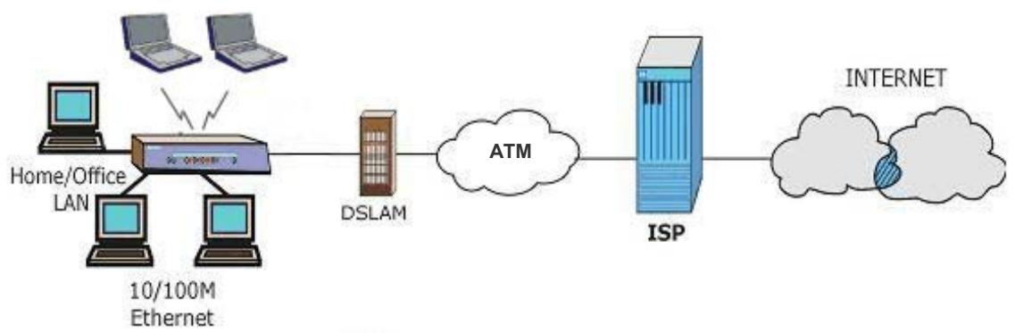
1.3.1 Internet Access
The Prestige is the ideal high-speed Internet access solution. Your Prestige supports the TCP/IP protocol, which the Internet uses exclusively. It is compatible with all major ADSL DSLAM (Digital Subscriber Line Access Multiplexer) providers. A DSLAM is a rack of ADSL line cards with data multiplexed into a backbone network interface/connection (for example, T1, OC3, DS3, ATM or Frame Relay). Think of it as the equivalent of a modem rack for ADSL. In addition, for Prestige 650H/HW, you can insert an optional wireless PCMICA card into the Prestige and allow wireless stations access to your network resources. A typical Internet access application is shown below.
flowchart
graph LR
    A["Home/Office LAN"] --> B["10/100M Ethernet"]
    C["Laptop"] --> B
    D["Laptop"] --> B
    E["Computer"] --> B
    F["Computer"] --> B
    B --> G["DSLAM"]
    G --> H["ATM"]
    H --> I["ISP"]
    I --> J["Internet"]
Figure 1-1 Prestige Internet Access Application
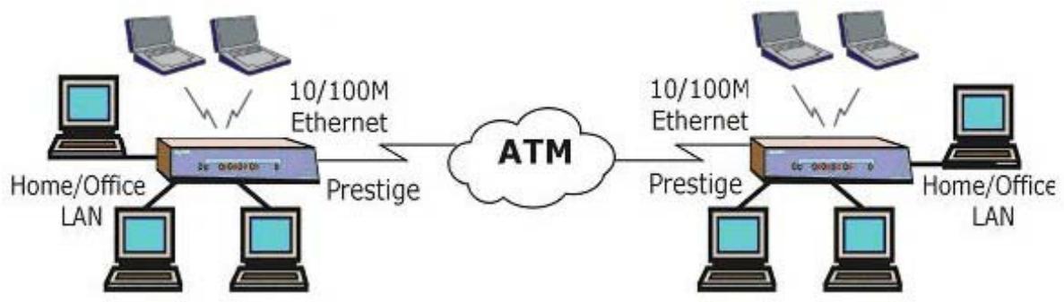
1.3.2 LAN to LAN Application
You can use the Prestige to connect two geographically dispersed networks over the ADSL line. A typical LAN-to-LAN application for your Prestige is shown as follows.
flowchart
graph LR
    A["Home/Office LAN"] --> B["10/100M Ethernet"]
    B --> C["ATM"]
    D["Home/Office LAN"] --> E["10/100M Ethernet"]
    E --> F["ATM"]
    B <--> G["Prestige"]
    E <--> H["Prestige"]
    G <--> I["10/100M Ethernet"]
    H <--> J["10/100M Ethernet"]
Figure 1-2 Prestige LAN-to-LAN Application
Chapter 2
Introducing the Web Configurator
This chapter describes how to access and navigate the web configurator.
2.1 Web Configurator Overview
The embedded web configurator allows you to manage the Prestige from anywhere through a browser such as Microsoft Internet Explorer or Netscape Navigator. Use Internet Explorer 6.0 and later or Netscape Navigator 7.0 and later versions with JavaScript enabled. It is recommended that you set your screen resolution to 1024 by 768 pixels
2.2 Accessing the Prestige Web Configurator
Step 1. Make sure your Prestige hardware is properly connected (refer to the Compact Guide or Read Me First).
Step 2. Prepare your computer/computer network to connect to the Prestige (refer to the Compact Guide or Read Me First).
Step 3. Launch your web browser.
Step 4. Type "192.168.1.1" as the URL.
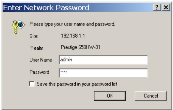
Step 5. An Enter Network Password window displays. Enter the user name (“admin” is the default), password (“1234” is the default) and click OK.
text_image
Enter Network Password Please type your user name and password. Site: 192.168.1.1 Realm Prestige 650HW-31 User Name admin Password xxxxx Save this password in your password list OK CancelFigure 2-1 Password Screen
Step 6. You should now see the Site Map screen.
The Prestige automatically times out after five minutes of inactivity. Simply log back into the Prestige if this happens to you.
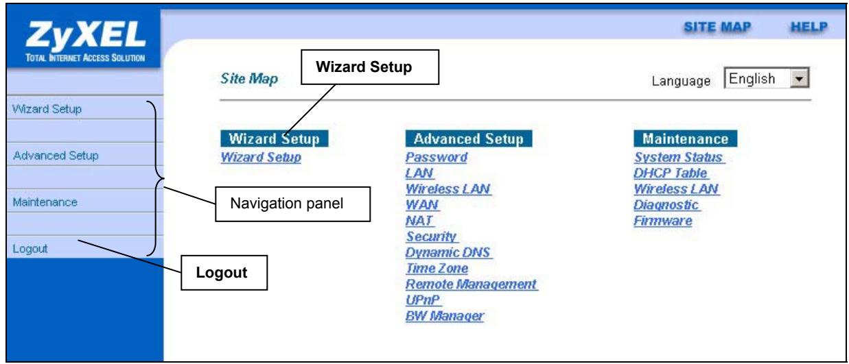
2.3 Navigating the Prestige Web Configurator
The following summarizes how to navigate the web configurator from the Site Map screen. Screens vary slightly for different Prestige models.
Select a language from the Language drop-down list box.
➢ Click Wizard Setup to begin a series of screens to configure your Prestige for the first time.
➢ Click a link under Advanced Setup to configure advanced Prestige features.
➢ Click a link under Maintenance to see Prestige performance statistics, upload firmware and back up, restore or upload a configuration file.
➢ Click SITE MAP to go to the Site Map screen.
➢ Click Logout in the navigation panel when you have finished a Prestige management session.
text_image
ZyXEL TOTAL INTERNET ACCESS SOLUTION Site Map Wizard Setup Language English Wizard Setup Wizard Setup Navigation panel Advanced Setup Password LAN Wireless LAN WAN NAT Security Dynamic DNS Time Zone Remote Management UPnP BW Manager Maintenance System Status DHCP Table Wireless LAN Diagnostic Firmware LogoutFigure 2-2 Web Configurator SITE MAP Screen
Click the HELP icon (located in the top right corner of most screens) to view embedded help.
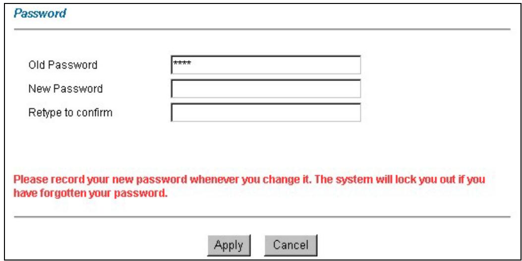
2.4 Configuring Password
It is highly recommended that you change the password for accessing the Prestige.
To change your Prestige's password, click Advanced Setup and then Password. The screen appears as shown.
text_image
Password Old Password ***** New Password Retype to confirm Please record your new password whenever you change it. The system will lock you out if you have forgotten your password. Apply CancelFigure 2-3 Password
The following table describes the labels in this screen.
Table 2-1 Password
| LABEL | DESCRIPTION |
| Old Password | Type the default password or the existing password you use to access the system in this field. |
| New Password | Type the new password in this field. |
| Retype to Confirm | Type the new password again in this field. |
| Apply | Click Apply to save your changes back to the Prestige. |
| Cancel | Click Cancel to begin configuring this screen afresh. |
2.5 Resetting the Prestige
If you forget your password or cannot access the Prestige, you will need to reload the factory-default configuration file or use the RESET button the back of the Prestige. Uploading this configuration file replaces the current configuration file with the factory-default configuration file. This means that you will lose all configurations that you had previously and the speed of the console port will be reset to the default of 9600bps with 8 data bit, no parity, one stop bit and flow control set to none. The password will be reset to “1234”, also.
2.5.1 Using The Reset Button
Step 1. Make sure the SYS LED is on (not blinking).
Step 2. Press the RESET button for five seconds, and then release it. When the SYS LED begins to blink, the defaults have been restored and the Prestige restarts.
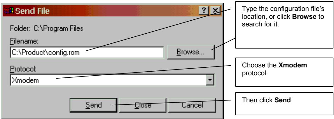
2.5.2 Uploading a Configuration File Via Console Port
Download the default configuration file from the ZyXEL FTP site, unzip it and save it in a folder.
Step 1. Turn off the Prestige, begin a terminal emulation software session and turn on the Prestige again. When you see the message "Press Any key to enter Debug Mode within 3 seconds", press any key to enter debug mode.
Step 2. Enter "atlc" after "Enter Debug Mode" message.
Step 3. Wait for "Starting XMODEM upload" message before activating Xmodem upload on your terminal. This is an example Xmodem configuration upload using HyperTerminal.
Step 4. Click Transfer, then Send File to display the following screen.
text_image
Send File Folder: C:\Program Files Filename: C:\Product\config.rom Browse... Type the configuration file's location, or click Browse to search for it. Choose the Xmodem protocol. Protocol: Xmodem Send Close Cancel Then click Send.Figure 2-4 Example Xmodem Upload
Step 5. After successful firmware upload, enter "atgo" to restart the router.
Chapter 3
Wizard Setup
This chapter provides information on the Wizard Setup screens in the web configurator.
3.1 Wizard Setup Introduction
Use the Wizard Setup screens to configure your system for Internet access settings and fill in the fields with the information in the Internet Account Information table of the Compact Guide or Read Me First. Your ISP may have already configured some of the fields in the wizard screens for you.
3.2 Encapsulation
Be sure to use the encapsulation method required by your ISP. The Prestige supports the following methods.
3.2.1 ENET ENCAP
The MAC Encapsulated Routing Link Protocol (ENET ENCAP) is only implemented with the IP network protocol. IP packets are routed between the Ethernet interface and the WAN interface and then formatted so that they can be understood in a bridged environment. For instance, it encapsulates routed Ethernet frames into bridged ATM cells. ENET ENCAP requires that you specify a gateway IP address in the Ethernet Encapsulation Gateway field in the second wizard screen. You can get this information from your ISP.
3.2.2 PPP over Ethernet
PPPoE provides access control and billing functionality in a manner similar to dial-up services using PPP. The Prestige bridges a PPP session over Ethernet (PPP over Ethernet, RFC 2516) from your computer to an ATM PVC (Permanent Virtual Circuit) which connects to ADSL Access Concentrator where the PPP session terminates. One PVC can support any number of PPP sessions from your LAN. For more information on PPPoE, see the appendix.
3.2.3 PPPoA
PPPoA stands for Point to Point Protocol over ATM Adaptation Layer 5 (AAL5). It provides access control and billing functionality in a manner similar to dial-up services using PPP. The Prestige encapsulates the PPP session based on RFC1483 and sends it through an ATM PVC (Permanent Virtual Circuit) to the Internet Service Provider's (ISP) DSLAM (digital access multiplexer). Please refer to RFC 2364 for more information on PPPoA. Refer to RFC 1661 for more information on PPP.
3.2.4 RFC 1483
RFC 1483 describes two methods for Multiprotocol Encapsulation over ATM Adaptation Layer 5 (AAL5). The first method allows multiplexing of multiple protocols over a single ATM virtual circuit (LLC-based multiplexing) and the second method assumes that each protocol is carried over a separate ATM virtual circuit (VC-based multiplexing). Please refer to the RFC for more detailed information.
3.3 Multiplexing
There are two conventions to identify what protocols the virtual circuit (VC) is carrying. Be sure to use the multiplexing method required by your ISP.
3.3.1 VC-based Multiplexing
In this case, by prior mutual agreement, each protocol is assigned to a specific virtual circuit; for example, VC1 carries IP, etc. VC-based multiplexing may be dominant in environments where dynamic creation of large numbers of ATM VCs is fast and economical.
3.3.2 LLC-based Multiplexing
In this case one VC carries multiple protocols with protocol identifying information being contained in each packet header. Despite the extra bandwidth and processing overhead, this method may be advantageous if it is not practical to have a separate VC for each carried protocol, for example, if charging heavily depends on the number of simultaneous VCs.
3.4 VPI and VCI
Be sure to use the correct Virtual Path Identifier (VPI) and Virtual Channel Identifier (VCI) numbers assigned to you. The valid range for the VPI is 0 to 255 and for the VCI is 32 to 65535 (0 to 31 is reserved for local management of ATM traffic). Please see the appendix for more information.
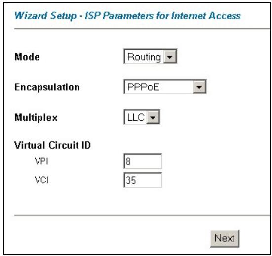
3.5 Wizard Setup Configuration: First Screen
In the SITE MAP screen click Wizard Setup to display the first wizard screen.
text_image
Wizard Setup - ISP Parameters for Internet Access Mode Routing Encapsulation PPPoE Multiplex LLC Virtual Circuit ID VPI 8 VCI 35 NextFigure 3-1 Wizard Screen 1
The following table describes the labels in this screen.
Table 3-1 Wizard Screen 1
| LABEL | DESCRIPTION |
| Mode | From the Mode drop-down list box, select Routing (default) if your ISP allows multiple computers to share an Internet account. Otherwise select Bridge. |
| Encapsulation | Select the encapsulation type your ISP uses from the Encapsulation drop-down list box.Choices vary depending on what you select in the Mode field.If you select Bridge in the Mode field, select either PPPoA or RFC 1483.If you select Routing in the Mode field, select PPPoA, RFC 1483, ENET ENCAP or PPPoE. |
| Multiplex | Select the multiplexing method used by your ISP from the Multiplex drop-down list box either VC-based or LLC-based. |
| Virtual Circuit ID | VPI (Virtual Path Identifier) and VCI (Virtual Channel Identifier) define a virtual circuit. Refer to the appendix for more information. |
| VPI | Enter the VPI assigned to you. This field may already be configured. |
| VCI | Enter the VCI assigned to you. This field may already be configured. |
Table 3-1 Wizard Screen 1
| LABEL | DESCRIPTION |
| Next | Click this button to go to the next wizard screen. The next wizard screen you see depends on what protocol you chose above. Click on the protocol link to see the next wizard screen for that protocol. |
3.6 IP Address and Subnet Mask
Similar to the way houses on a street share a common street name, so too do computers on a LAN share one common network number.
Where you obtain your network number depends on your particular situation. If the ISP or your network administrator assigns you a block of registered IP addresses, follow their instructions in selecting the IP addresses and the subnet mask.
If the ISP did not explicitly give you an IP network number, then most likely you have a single user account and the ISP will assign you a dynamic IP address when the connection is established. If this is the case, it is recommended that you select a network number from 192.168.0.0 to 192.168.255.0 and you must enable the Network Address Translation (NAT) feature of the Prestige. The Internet Assigned Number Authority (IANA) reserved this block of addresses specifically for private use; please do not use any other number unless you are told otherwise. Let's say you select 192.168.1.0 as the network number; which covers 254 individual addresses, from 192.168.1.1 to 192.168.1.254 (zero and 255 are reserved). In other words, the first three numbers specify the network number while the last number identifies an individual computer on that network.
Once you have decided on the network number, pick an IP address that is easy to remember, for instance, 192.168.1.1, for your Prestige, but make sure that no other device on your network is using that IP address.
The subnet mask specifies the network number portion of an IP address. Your Prestige will compute the subnet mask automatically based on the IP address that you entered. You don't need to change the subnet mask computed by the Prestige unless you are instructed to do otherwise.
3.7 IP Address Assignment
A static IP is a fixed IP that your ISP gives you. A dynamic IP is not fixed; the ISP assigns you a different one each time. The Single User Account feature can be enabled or disabled if you have either a dynamic or static IP. However the encapsulation method assigned influences your choices for IP address and ENET ENCAP Gateway.
3.7.1 IP Assignment with PPPoA or PPPoE Encapsulation
If you have a dynamic IP, then the IP Address and ENET ENCAP Gateway fields are not applicable (N/A). If you have a static IP, then you only need to fill in the IP Address field and not the ENET ENCAP Gateway field.
3.7.2 IP Assignment with RFC 1483 Encapsulation
In this case the IP Address Assignment must be static with the same requirements for the IP Address and ENET ENCAP Gateway fields as stated above.
3.7.3 IP Assignment with ENET ENCAP Encapsulation
In this case you can have either a static or dynamic IP. For a static IP you must fill in all the IP Address and ENET ENCAP Gateway fields as supplied by your ISP. However for a dynamic IP, the Prestige acts as a DHCP client on the WAN port and so the IP Address and ENET ENCAP Gateway fields are not applicable (N/A) as the DHCP server assigns them to the Prestige.
3.7.4 Private IP Addresses
Every machine on the Internet must have a unique address. If your networks are isolated from the Internet, for example, only between your two branch offices, you can assign any IP addresses to the hosts without problems. However, the Internet Assigned Numbers Authority (IANA) has reserved the following three blocks of IP addresses specifically for private networks:
10.0.0.0 - 10.255.255.255
172.16.0.0 - 172.31.255.255
192.168.0.0 - 192.168.255.255
You can obtain your IP address from the IANA, from an ISP or it can be assigned from a private network. If you belong to a small organization and your Internet access is through an ISP, the ISP can provide you with the Internet addresses for your local networks. On the other hand, if you are part of a much larger organization, you should consult your network administrator for the appropriate IP addresses.
Regardless of your particular situation, do not create an arbitrary IP address; always follow the guidelines above. For more information on address assignment, please refer to RFC 1597, Address Allocation for Private Internets and RFC 1466, Guidelines for Management of IP Address Space.
3.8 Nailed-Up Connection (PPP)
A nailed-up connection is a dial-up line where the connection is always up regardless of traffic demand. The Prestige does two things when you specify a nailed-up connection. The first is that idle timeout is disabled. The second is that the Prestige will try to bring up the connection when turned on and whenever the connection is down. A nailed-up connection can be very expensive for obvious reasons.
Do not specify a nailed-up connection unless your telephone company offers flat-rate service or you need a constant connection and the cost is of no concern
3.9 NAT
NAT (Network Address Translation - NAT, RFC 1631) is the translation of the IP address of a host in a packet, for example, the source address of an outgoing packet, used within one network to a different IP address known within another network.
3.10 Wizard Setup Configuration: Second Screen
The second wizard screen varies depending on what mode and encapsulation type you use. All screens shown are with routing mode. Configure the fields and click Next to continue.
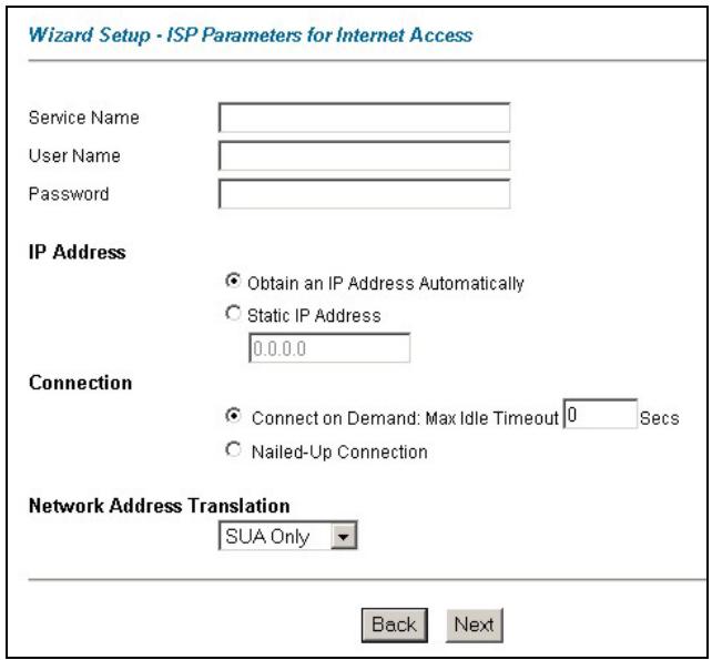
3.10.1 PPPoE
Select PPPoE from the Encapsulation drop-down list box in the first wizard screen to display the screen as shown.
text_image
Wizard Setup · ISP Parameters for Internet Access Service Name User Name Password IP Address Obtain an IP Address Automatically Static IP Address 0.0.0.0 Connection Connect on Demand: Max Idle Timeout 0 Secs Nailed-Up Connection Network Address Translation SUA Only Back NextFigure 3-2 Internet Connection with PPPoE
The following table describes the labels in this screen.
Table 3-2 Internet Connection with PPPoE
| LABEL | DESCRIPTION |
| Service Name | Type the name of your PPPoE service here. |
| User Name | Configure User Name and Password fields for PPPoA and PPPoE encapsulation only.Enter the user name exactly as your ISP assigned. If assigned a name in the formuser@domainwhere domain identifies a service name, then enter both components exactly as given. |
| Password | Enter the password associated with the user name above. |
| IP Address | A static IP address is a fixed IP that your ISP gives you. A dynamic IP address is not fixed;the ISP assigns you a different one each time you connect to the Internet. The Single User Account feature can be used with either a dynamic or static IP address.Select Obtain an IP Address Automatically if you have a dynamic IP address; otherwise select Static IP Address and type your ISP assigned IP address in the IP Address text box below. |
Table 3-2 Internet Connection with PPPoE
| LABEL | DESCRIPTION |
| Connection | SelectConnect on Demandwhen you don't want the connection up all the time and specify an idle time-out (in seconds) in theMax. Idle Timeoutfield. The default setting selectsConnection on Demandwith 0 as the idle time-out, which means the Internet session will not timeout.SelectNailed-Up Connectionwhen you want your connection up all the time. The Prestige will try to bring up the connection automatically if it is disconnected.The schedule rule(s) in SMT menu 26 has priority over yourConnectionsettings. |
| Network Address Translation | SelectNone, SUA Onlyor Full Featurefrom the drop-sown list box. Refer to the NAT chapter for more details. |
| Back | ClickBackto go back to the first wizard screen. |
| Next | ClickNextto continue to the next wizard screen. |
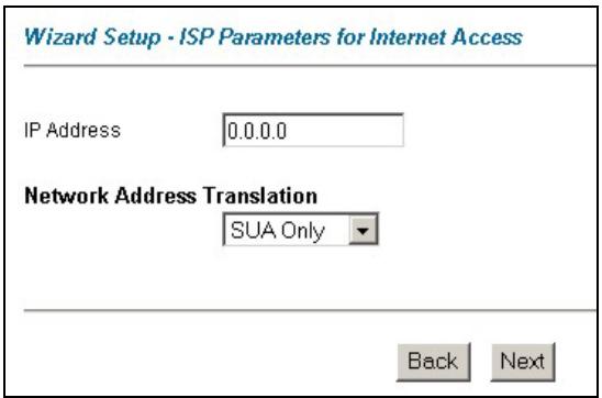
3.10.2 RFC 1483
Select RFC 1483 from the Encapsulation drop-down list box in the first wizard screen to display the screen as shown.
text_image
Wizard Setup - ISP Parameters for Internet Access IP Address 0.0.0.0 Network Address Translation SUA Only Back NextFigure 3-3 Internet Connection with RFC 1483
The following table describes the labels in this screen.
Table 3-3 Internet Connection with RFC 1483
| LABEL | DESCRIPTION |
| IP Address | This field is available if you selectRoutingin theModefield.Type your ISP assigned IP address in this field. |
| Network Address Translation | Select None, SUA Onlyor Full Featurefrom the drop-sown list box. Refer to the NAT chapter for more details. |
| Back | ClickBackto go back to the first wizard screen. |
| Next | ClickNextto continue to the next wizard screen. |
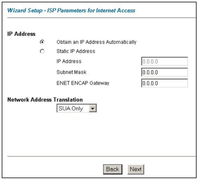
3.10.3 ENET ENCAP
Select ENET ENCAP from the Encapsulation drop-down list box in the first wizard screen to display the screen as shown.
text_image
Wizard Setup - ISP Parameters for Internet Access IP Address Obtain an IP Address Automatically Static IP Address IP Address 0.0.0.0 Subnet Mask 0.0.0.0 ENET ENCAP Gateway 0.0.0.0 Network Address Translation SUA Only Back NextFigure 3-4 Internet Connection with ENET ENCAP
The following table describes the labels in this screen.
Table 3-4 Internet Connection with ENET ENCAP
| LABEL | DESCRIPTION |
| IP Address | A static IP address is a fixed IP that your ISP gives you. A dynamic IP address is not fixed; the ISP assigns you a different one each time you connect to the Internet. The Single User Account feature can be used with either a dynamic or static IP address.Select Obtain an IP Address Automatically if you have a dynamic IP address; otherwise select Static IP Address and type your ISP assigned IP address in the IP Address text box below. |
| Subnet Mask | Enter a subnet mask in dotted decimal notation.Refer to the IP Subnetting appendix to calculate a subnet mask If you are implementing subnetting. |
| ENET ENCAP Gateway | You must specify a gateway IP address (supplied by your ISP) when you use ENET ENCAP in the Encapsulation field in the previous screen. |
| Network Address Translation | Select None, SUA Only or Full Feature from the drop-sown list box. Refer to the NAT chapter for more details. |
| Back | Click Back to go back to the first wizard screen. |
| Next | Click Next to continue to the next wizard screen. |
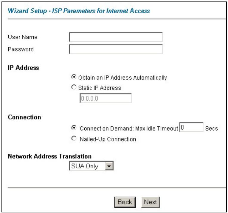
3.10.4 PPPoA
Select PPPoA from the Encapsulation drop-down list box in the first wizard screen to display the screen as shown.
text_image
Wizard Setup - ISP Parameters for Internet Access User Name Password IP Address Obtain an IP Address Automatically Static IP Address 0.0.0.0 Connection Connect on Demand: Max Idle Timeout 0 Secs Nailed-Up Connection Network Address Translation SUA Only Back NextFigure 3-5 Internet Connection with PPPoA
The following table describes the labels in this screen.
Table 3-5 Internet Connection with PPPoA
| LABEL | DESCRIPTION |
| User Name | Enter the user name exactly as your ISP assigned. If assigned a name in the formuser@domainwhere domain identifies a service name, then enter both components exactly as given. |
| Password | Enter the password associated with the user name above. |
Table 3-5 Internet Connection with PPPoA
| LABEL | DESCRIPTION |
| IP Address | This option is available if you selectRoutingin theModefield.A static IP address is a fixed IP that your ISP gives you. A dynamic IP address is not fixed; the ISP assigns you a different one each time you connect to the Internet. The Single User Account feature can be used with either a dynamic or static IP address.ClickObtain an IP Address Automaticallyif you have a dynamic IP address; otherwise clickStatic IP Addressand type your ISP assigned IP address in theIP Addresstext box below. |
| Connection | SelectConnect on Demandwhen you don't want the connection up all the time and specify an idle time-out (in seconds) in theMax.Idle Timeoutfield. The default setting selectsConnection on Demandwith 0 as the idle time-out, which means the Internet session will not timeout.SelectNailed-Up Connectionwhen you want your connection up all the time. The Prestige will try to bring up the connection automatically if it is disconnected.The schedule rule(s) in SMT menu 26 has priority over yourConnectionsettings. |
| Network Address Translation | This option is available if you selectRoutingin theModefield.Select None, SUA Onlyor Full Featurefrom the drop-sown list box. Refer to the NAT chapter for more details. |
| Back | ClickBackto go back to the first wizard screen. |
| Next | ClickNextto continue to the next wizard screen. |
3.11 DHCP Setup
DHCP (Dynamic Host Configuration Protocol, RFC 2131 and RFC 2132) allows individual clients to obtain TCP/IP configuration at start-up from a server. You can configure the Prestige as a DHCP server or disable it. When configured as a server, the Prestige provides the TCP/IP configuration for the clients. If you turn DHCP service off, you must have another DHCP server on your LAN, or else the computer must be manually configured.
3.11.1 IP Pool Setup
The Prestige is pre-configured with a pool of 32 IP addresses starting from 192.168.1.33 to 192.168.1.64 for the client machines. This leaves 31 IP addresses, 192.168.1.2 to 192.168.1.32 (excluding the Prestige itself which has a default IP of 192.168.1.1) for other server machines, for example, server for mail, FTP, telnet, web, etc., that you may have.
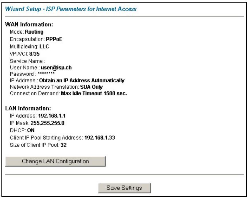
3.12 Wizard Setup Configuration: Third Screen
Verify the settings in the screen shown next. To change the LAN information on the Prestige, click Change LAN Configurations. Otherwise click Save Settings to save the configuration and skip to section 3.13.
text_image
Wizard Setup - ISP Parameters for Internet Access WAN Information: Mode: Routing Encapsulation: PPPoE Multiplexing: LLC VPI/VCI: 8/35 Service Name : User Name : user@isp.ch Password : ****** IP Address : Obtain an IP Address Automatically Network Address Translation: SUA Only Connect on Demand: Max Idle Timeout 1500 sec. LAN Information: IP Address: 192.168.1.1 IP Mask: 255.255.255.0 DHCP: ON Client IP Pool Starting Address: 192.168.1.33 Size of Client IP Pool: 32 Change LAN Configuration Save SettingsFigure 3-6 Wizard Screen 3
If you want to change your Prestige LAN settings, click Change LAN Configuration to display the screen as shown next.
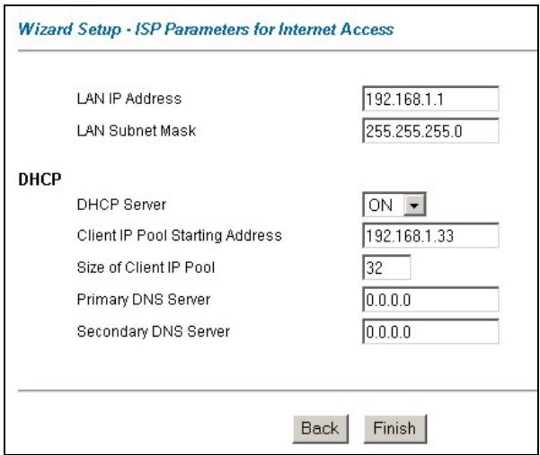
text_image
Wizard Setup - ISP Parameters for Internet Access LAN IP Address 192.168.1.1 LAN Subnet Mask 255.255.255.0 DHCP DHCP Server ON Client IP Pool Starting Address 192.168.1.33 Size of Client IP Pool 32 Primary DNS Server 0.0.0.0 Secondary DNS Server 0.0.0.0 Back FinishFigure 3-7 Wizard : LAN Configuration
The following table describes the labels in this screen.
Table 3-6 Wizard : LAN Configuration
| LABEL | DESCRIPTION |
| LAN IP Address | Enter the IP address of your Prestige in dotted decimal notation, for example, 192.168.1.1 (factory default).If you changed the Prestige's LAN IP address, you must use the new IP address if you want to access the web configurator again. |
| LAN Subnet Mask | Enter a subnet mask in dotted decimal notation. |
| DHCP | |
| DHCP Server | From the DHCP Server drop-down list box, select On to allow your Prestige to assign IP addresses, an IP default gateway and DNS servers to computer systems that support the DHCP client. Select Off to disable DHCP server.When DHCP server is used, set the following items: |
Table 3-6 Wizard : LAN Configuration
| LABEL | DESCRIPTION |
| Client IP Pool Starting Address | This field specifies the first of the contiguous addresses in the IP address pool. |
| Size of Client IP Pool | This field specifies the size or count of the IP address pool. |
| Primary DNS Server | Enter the IP addresses of the DNS servers. The DNS servers are passed to the DHCP clients along with the IP address and the subnet mask. |
| Secondary DNS Server | As above. |
| Back | Click Back to go back to the previous screen. |
| Finish | Click Finish to save the settings and proceed to the next wizard screen. |
3.13 Wizard Setup Configuration: Connection Tests
The Prestige automatically tests the connection to the computer(s) connected to the LAN ports. To test the connection from the Prestige to the ISP, click Start Diagnose. Otherwise click Return to Main Menu to go back to the Site Map screen.
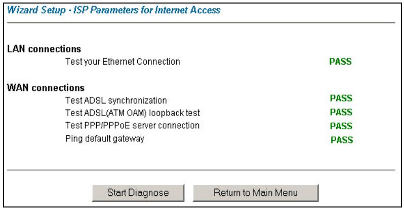
text_image
Wizard Setup - ISP Parameters for Internet Access LAN connections Test your Ethernet Connection PASS WAN connections Test ADSL synchronization PASS Test ADSL(ATM OAM) loopback test PASS Test PPP/PPPoE server connection PASS Ping default gateway PASS Start Diagnose Return to Main MenuFigure 3-8 Wizard Screen 4
3.14 Test Your Internet Connection
Launch your web browser and navigate to www.zyxel.com. Internet access is just the beginning. Refer to the rest of this User's Guide for more detailed information on the complete range of Prestige features. If you cannot access the Internet, open the web configurator again to confirm that the Internet settings you configured in the Wizard Setup are correct.
Part II:
LAN, Wireless LAN and WAN
This part covers the LAN (Local Area Network), wireless LAN and WAN setup.
Chapter 4
LAN Setup
This chapter describes how to configure LAN settings.
4.1 LAN Overview
A Local Area Network (LAN) is a shared communication system to which many computers are attached. A LAN is a computer network limited to the immediate area, usually the same building or floor of a building. The LAN screens can help you configure a LAN DHCP server and manage IP addresses.
4.1.1 LANs, WANs and the Prestige
The actual physical connection determines whether the Prestige ports are LAN or WAN ports. There are two separate IP networks, one inside, the LAN network; the other outside: the WAN network as shown next:
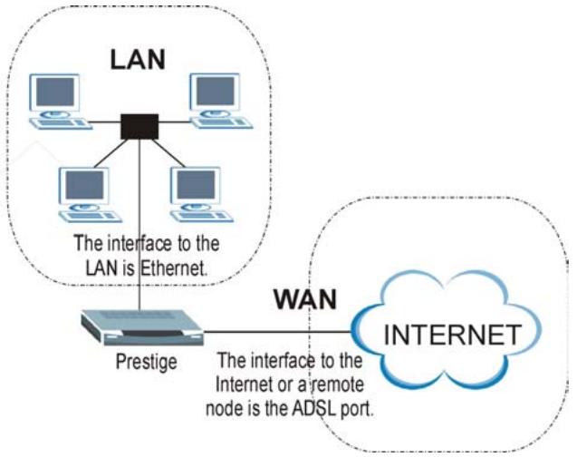
flowchart
graph TD
    A["LAN"] --> B["Prestige"]
    B --> C["Internet"]
    D["Computer 1"] --> E["Computer 2"]
    F["Computer 3"] --> G["Computer 4"]
    H["Computer 5"] --> I["Computer 6"]
    J["Computer 7"] --> K["Computer 8"]
    L["Computer 9"] --> M["Computer 10"]
    N["Computer 11"] --> O["Computer 12"]
    P["Computer 13"] --> Q["Computer 14"]
    R["Computer 15"] --> S["Computer 16"]
    T["Computer 17"] --> U["Computer 18"]
    V["Computer 19"] --> W["Computer 20"]
    X["Computer 21"] --> Y["Computer 22"]
    Z["Computer 23"] --> AA["Computer 24"]
    AB["Computer 25"] --> AC["Computer 26"]
    AD["Computer 27"] --> AE["Computer 28"]
    AF["Computer 29"] --> AG["Computer 30"]
    AH["Computer 31"] --> AI["Computer 32"]
    AJ["Computer 33"] --> AK["Computer 34"]
    AL["Computer 35"] --> AM["Computer 36"]
    AN["Computer 37"] --> AO["Computer 38"]
    AP["Computer 39"] --> AQ["Computer 40"]
    AR["Computer 41"] --> AS["Computer 42"]
    AT["Computer 43"] --> AU["Computer 44"]
    AV["Computer 45"] --> AW["Computer 46"]
    AX["Computer 47"] --> AY["Computer 48"]
    AZ["Computer 49"] --> BA["Computer 50"]
    BB["Computer 51"] --> BC["Computer 52"]
    BD["Computer 53"] --> BE["Computer 54"]
    BF["Computer 55"] --> BG["Computer 56"]
    BH["Computer 57"] --> BI["Computer 58"]
    BJ["Computer 59"] --> BK["Computer 60"]
    BL["Computer 61"] --> BM["Computer 62"]
    BN["Computer 63"] --> BO["Computer 64"]
    BP["Computer 65"] --> BQ["Computer 66"]
    BR["Computer 67"] --> BS["Computer 68"]
    BT["Computer 69"] --> BU["Computer 70"]
    BV["Computer 71"] --> BW["Computer 72"]
    BX["Computer 73"] --> BY["Computer 74"]
    BZ["Computer 75"] --> CA["Computer 76"]
    CB["Computer 77"] --> CC["Computer 78"]
    DD["Computer 79"] --> EE["Computer 80"]
    FF["Computer 81"] --> DG["Computer 82"]
    DH["Computer 83"] --> DI["Computer 84"]
    DJ["Computer 84"] --> DK["Computer 85"]
    DL["Computer 85"] --> DV["Computer 86"]
    DW["Computer 87"] --> DX["Computer 88"]
    DXN["WAN"] --> DXN
    DXN --> DXN
Figure 4-1 LAN and WAN IP Addresses
4.2 DNS Server Address
DNS (Domain Name System) is for mapping a domain name to its corresponding IP address and vice versa, for example, the IP address of www.zyxel.com is 204.217.0.2. The DNS server is extremely important because without it, you must know the IP address of a machine before you can access it. The DNS server addresses that you enter in the DHCP setup are passed to the client machines along with the assigned IP address and subnet mask.
There are two ways that an ISP disseminates the DNS server addresses. The first is for an ISP to tell a customer the DNS server addresses, usually in the form of an information sheet, when s/he signs up. If your ISP gives you the DNS server addresses, enter them in the DNS Server fields in DHCP Setup, otherwise, leave them blank.
Some ISP's choose to pass the DNS servers using the DNS server extensions of PPP IPCP (IP Control Protocol) after the connection is up. If your ISP did not give you explicit DNS servers, chances are the DNS servers are conveyed through IPCP negotiation. The Prestige supports the IPCP DNS server extensions through the DNS proxy feature.
If the Primary and Secondary DNS Server fields in DHCP Setup are not specified, for instance, left as 0.0.0.0, the Prestige tells the DHCP clients that it itself is the DNS server. When a computer sends a DNS query to the Prestige, the Prestige forwards the query to the real DNS server learned through IPCP and relays the response back to the computer.
Please note that DNS proxy works only when the ISP uses the IPCP DNS server extensions. It does not mean you can leave the DNS servers out of the DHCP setup under all circumstances. If your ISP gives you explicit DNS servers, make sure that you enter their IP addresses in the DHCP Setup menu. This way, the Prestige can pass the DNS servers to the computers and the computers can query the DNS server directly without the Prestige's intervention.
4.3 DNS Server Address Assignment
Use DNS (Domain Name System) to map a domain name to its corresponding IP address and vice versa. The DNS server is extremely important because without it, you must know the IP address of a computer before you can access it.
There are two ways that an ISP disseminates the DNS server addresses.
- The ISP tells you the DNS server addresses, usually in the form of an information sheet, when you sign up. If your ISP gives you DNS server addresses, enter them in the DNS Server fields in DHCP Setup.
- Leave the DNS Server fields in DHCP Setup blank (for example 0.0.0.0). The Prestige acts as a DNS proxy when this field is blank.
4.4 LAN TCP/IP
The Prestige has built-in DHCP server capability that assigns IP addresses and DNS servers to systems that support DHCP client capability.
4.4.1 Factory LAN Defaults
The LAN parameters of the Prestige are preset in the factory with the following values:
IP address of 192.168.1.1 with subnet mask of 255.255.255.0 (24 bits)
DHCP server enabled with 32 client IP addresses starting from 192.168.1.33.
These parameters should work for the majority of installations. If your ISP gives you explicit DNS server address(es), read the embedded web configurator help regarding what fields need to be configured.
4.4.2 IP Address and Subnet Mask
Refer to the IP Address and Subnet Mask section in the Wizard Setup chapter for this information.
4.4.3 RIP Setup
RIP (Routing Information Protocol) allows a router to exchange routing information with other routers. The RIP Direction field controls the sending and receiving of RIP packets. When set to:
- Both - the Prestige will broadcast its routing table periodically and incorporate the RIP information that it receives.
- In Only - the Prestige will not send any RIP packets but will accept all RIP packets received.
- Out Only - the Prestige will send out RIP packets but will not accept any RIP packets received.
- None - the Prestige will not send any RIP packets and will ignore any RIP packets received.
The Version field controls the format and the broadcasting method of the RIP packets that the Prestige sends (it recognizes both formats when receiving). RIP-1 is universally supported; but RIP-2 carries more information. RIP-1 is probably adequate for most networks, unless you have an unusual network topology.
Both RIP-2B and RIP-2M sends the routing data in RIP-2 format; the difference being that RIP-2B uses subnet broadcasting while RIP-2M uses multicasting.
4.4.4 Multicast
Traditionally, IP packets are transmitted in one of either two ways - Unicast (1 sender - 1 recipient) or Broadcast (1 sender - everybody on the network). Multicast delivers IP packets to a group of hosts on the network - not everybody and not just 1.
IGMP (Internet Group Multicast Protocol) is a network-layer protocol used to establish membership in a Multicast group - it is not used to carry user data. IGMP version 2 (RFC 2236) is an improvement over version 1 (RFC 1112) but IGMP version 1 is still in wide use. If you would like to read more detailed information about interoperability between IGMP version 2 and version 1, please see sections 4 and 5 of RFC 2236. The class D IP address is used to identify host groups and can be in the range 224.0.0.0 to 239.255.255.255. The address 224.0.0.0 is not assigned to any group and is used by IP multicast computers. The address 224.0.0.1 is used for query messages and is assigned to the permanent group of all IP hosts (including gateways). All hosts must join the 224.0.0.1 group in order to participate in IGMP. The address 224.0.0.2 is assigned to the multicast routers group.
The Prestige supports both IGMP version 1 (IGMP-v1) and IGMP version 2 (IGMP-v2). At start up, the Prestige queries all directly connected networks to gather group membership. After that, the Prestige periodically updates this information. IP multicasting can be enabled/disabled on the Prestige LAN and/or WAN interfaces in the web configurator (LAN; WAN). Select None to disable IP multicasting on these interfaces.
4.5 Configuring LAN
Click LAN to open the following screen.
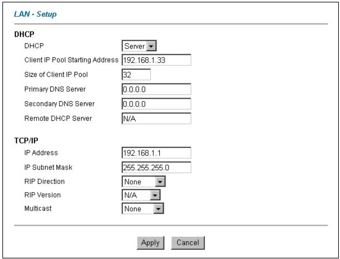
text_image
LAN - Setup DHCP DHCP Server Client IP Pool Starting Address 192.168.1.33 Size of Client IP Pool 32 Primary DNS Server 0.0.0.0 Secondary DNS Server 0.0.0.0 Remote DHCP Server N/A TCP/IP IP Address 192.168.1.1 IP Subnet Mask 255.255.255.0 RIP Direction None RIP Version N/A Multicast None Apply CancelFigure 4-2 LAN
The following table describes the labels in this screen.
Table 4-1 LAN
| LABEL | DESCRIPTION |
| DHCP | |
Table 4-1 LAN
| LABEL | DESCRIPTION |
| DHCP | If set to Server, your Prestige can assign IP addresses, an IP default gateway and DNS servers to Windows 95, Windows NT and other systems that support the DHCP client.If set to None, the DHCP server will be disabled.If set to Relay, the Prestige acts as a surrogate DHCP server and relays DHCP requests and responses between the remote server and the clients. Enter the IP address of the actual, remote DHCP server in the Remote DHCP Server field in this case.When DHCP is used, the following items need to be set: |
| Client IP Pool Starting Address | This field specifies the first of the contiguous addresses in the IP address pool. |
| Size of Client IP Pool | This field specifies the size or count of the IP address pool. |
| Primary DNS Server | Enter the IP addresses of the DNS servers. The DNS servers are passed to the DHCP clients along with the IP address and the subnet mask. |
| Secondary DNS Server | As above. |
| Remote DHCP Server | If Relay is selected in the DHCP field above then enter the IP address of the actual remote DHCP server here. |
| TCP/IP | |
| IP Address | Enter the IP address of your Prestige in dotted decimal notation, for example, 192.168.1.1 (factory default). |
| IP Subnet Mask | Type the subnet mask assigned to you by your ISP (if given). |
| RIP Direction | Select the RIP direction from None, Both, In Only and Out Only. |
| RIP Version | Select the RIP version from RIP-1, RIP-2B and RIP-2M. |
| Multicast | IGMP (Internet Group Multicast Protocol) is a session-layer protocol used to establish membership in a multicast group. The Prestige supports both IGMP version 1 (IGMP-v1) and IGMP-v2. Select None to disable it. |
| Apply | Click this button to save these settings back to the Prestige. |
| Cancel | Click this button to reset the fields in this screen. |
Chapter 5
Wireless LAN Setup
This chapter discusses how to configure Wireless LAN on the Prestige. This chapter is only applicable to the Prestige 650H and Prestige 650HW.
5.1 Wireless LAN Overview
This section introduces the wireless LAN and some basic configurations. Wireless LANs can be as simple as two computers with wireless LAN cards communicating in a peer-to-peer network or as complex as a number of computers with wireless LAN cards communicating through access points which bridge network traffic to the wired LAN.
The WLAN screens are only available when a WLAN card is installed.
5.1.1 Additional Installation Requirements for Using 802.1x
A computer with an IEEE 802.11b wireless LAN card and equipped with a web browser (with JavaScript enabled) and/or Telnet.
A wireless station computer must be running IEEE 802.1x-compliant software. Currently, this is offered in Windows XP.
➢ An optional network RADIUS server for remote user authentication and accounting.
5.1.2 Channel
The range of radio frequencies used by IEEE 802.11b wireless devices is called a “channel”. Channels available depend on your geographical area. You may have a choice of channels (for your region) so you should use a different channel than an adjacent AP (access point) to reduce interference. Interference occurs when radio signals from different access points overlap causing interference and degrading performance.
Adjacent channels partially overlap however. To avoid interference due to overlap, your AP should be on a channel at least five channels away from a channel that an adjacent AP is using. For example, if your region has 11 channels and an adjacent AP is using channel 1, then you need to select a channel between 6 or 11.
5.1.3 ESS ID
An Extended Service Set (ESS) is a group of access points or wireless gateways connected to a wired LAN on the same subnet. An ESS ID uniquely identifies each set. All access points or wireless gateways and their associated wireless stations in the same set must have the same ESSID.
5.1.4 RTS/CTS
A hidden node occurs when two stations are within range of the same access point, but are not within range of each other. The following figure illustrates a hidden node. Both stations (STA) are within range of the access point (AP) or wireless gateway, but out-of-range of each other, so they cannot “hear” each other, that is they do not know if the channel is currently being used. Therefore, they are considered hidden from each other.
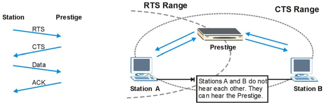
flowchart
graph TD
    subgraph_Stations_A["Station A"]
        RTS1["RTS"] --> Prestige1["Prestige"]
        CTS1["CTS"] --> Prestige1
        Data1["Data"] --> Prestige1
        ACK1["ACK"] --> Prestige1
    end
    subgraph_Stations_B["Station B"]
        Prestige2["Prestige"] --> CTS2["CTS Range"]
        CTS2 --> Prestige2
        Prestige2 --> Station3["Station A"]
        Prestige2 --> Station4["Station B"]
        Prestige2 --> CTS3["CTS Range"]
        CTS3 --> Prestige3["Prestige"]
        CTS3 --> CTS4["CTS Range"]
        CTS4 --> Station5["Station A and B"]
        CTS4 --> Station6["Station B"]
    end
    Note: Stations A and B do not hear each other. They can hear the Prestige.
Figure 5-1 RTS/CTS
When station A sends data to the Prestige, it might not know that the station B is already using the channel. If these two stations send data at the same time, collisions may occur when both sets of data arrive at the AP at the same time, resulting in a loss of messages for both stations.
RTS/CTS is designed to prevent collisions due to hidden nodes. An RTS/CTS defines the biggest size data frame you can send before an RTS (Request To Send)/CTS (Clear to Send) handshake is invoked.
When a data frame exceeds the RTS/CTS value you set (between 0 to 2432 bytes), the station that wants to transmit this frame must first send an RTS (Request To Send) message to the AP for permission to send it. The AP then responds with a CTS (Clear to Send) message to all other stations within its range to notify them to defer their transmission. It also reserves and confirms with the requesting station the time frame for the requested transmission.
Stations can send frames smaller than the specified RTS/CTS directly to the AP without the RTS (Request To Send)/CTS (Clear to Send) handshake.
You should only configure RTS/CTS if the possibility of hidden nodes exists on your network and the “cost” of resending large frames is more than the extra network overhead involved in the RTS (Request To Send)/CTS (Clear to Send) handshake.
If the RTS/CTS value is greater than the Fragmentation Threshold value (see next), then the RTS (Request To Send)/CTS (Clear to Send) handshake will never occur as data frames will be fragmented before they reach RTS/CTS size.
Enabling the RTS Threshold causes redundant network overhead that could negatively affect the throughput performance instead of providing a remedy.
5.1.5 Fragmentation Threshold
A Fragmentation Threshold is the maximum data fragment size (between 256 and 2432 bytes) that can be sent in the wireless network before the Prestige will fragment the packet into smaller data frames.
A large Fragmentation Threshold is recommended for networks not prone to interference while you should set a smaller threshold for busy networks or networks that are prone to interference.
If the Fragmentation Threshold value is smaller than the RTS/CTS value (see previously) you set then the RTS (Request To Send)/CTS (Clear to Send) handshake will never occur as data frames will be fragmented before they reach RTS/CTS size.
5.2 Levels of Security
Wireless security is vital to your network to protect wireless communication between wireless stations, access points and the wired network.
The figure below shows the possible wireless security levels on your Prestige. The highest security level relies on EAP (Extensible Authentication Protocol) for authentication and utilizes dynamic WEP key exchange. It requires interaction with a RADIUS (Remote Authentication Dial-In User Service) server either on the WAN or your LAN to provide authentication service for wireless stations.
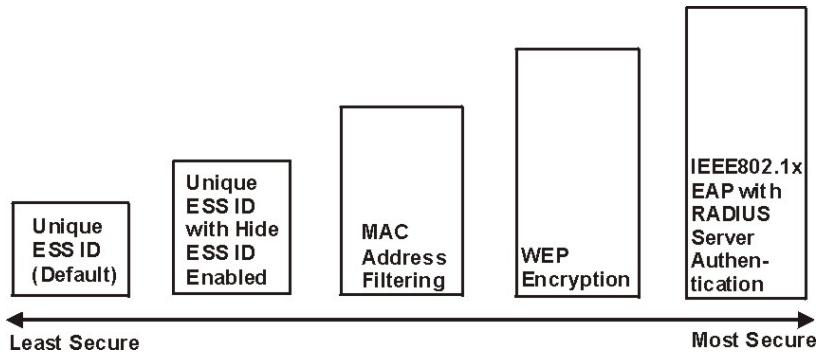
flowchart
graph LR
    A["Unique ESS ID (Default)"] --> B["Unique ESS ID with Hide ESS ID Enabled"]
    B --> C["MAC Address Filtering"]
    C --> D["WEP Encryption"]
    D --> E["IEEE802.1x EAP with RADIUS Server Authentication"]
    style A fill:#f9f,stroke:#333
    style B fill:#f9f,stroke:#333
    style C fill:#f9f,stroke:#333
    style D fill:#f9f,stroke:#333
    style E fill:#f9f,stroke:#333
Figure 5-2 Prestige Wireless Security Levels
If you do not enable any wireless security on your Prestige, your network is accessible to any wireless networking device that is within range.
Use the Prestige web configurator to configurator to set up your wireless LAN security settings. Refer to the chapter on using the Prestige web configurator to see how to access the web configurator.
5.3 Data Encryption with WEP
WEP encryption scrambles the data transmitted between the wireless stations and the access points to keep network communications private. It encrypts unicast and multicast communications in a network. Both the wireless stations and the access points must use the same WEP key for data encryption and decryption.
Your Prestige allows you to configure up to four 64-bit or 128-bit WEP keys but only one key can be enabled at any one time.
5.4 Inserting a PCMCIA Wireless LAN Card
Use a ZyAIR series wireless LAN PCMCIA card to add wireless LAN capabilities.
Step 1. Turn off the Prestige.
Never insert or remove a wireless LAN card when the Prestige is turned on.
Step 2. Locate the slot labeled Wireless LAN on the Prestige.
Step 3. With its pin connector facing the slot and the LED side facing upwards, slide the ZyAIR wireless LAN card into the slot.
Never force, bend or twist the wireless LAN card into the slot.
Step 4. Turn on the Prestige. The WLAN LED should turn on.
5.5 Configuring Wireless LAN
If you are configuring the Prestige from a computer connected to the wireless LAN and you change the Prestige's ESSID or WEP settings, you will lose your wireless connection when you press Apply to confirm. You must then change the wireless settings of your computer to match the Prestige's new settings.
Click Wireless LAN, Wireless to open the Wireless screen.
Wireless LAN-Wireless
ESSID
Wireless
Hide ESSID
No
Channel ID
Channel-01 2412MHz
RTS/CTS Threshold
0 (0 \~ 2432)
Fragmentation Threshold
2432 (256 \~ 2432)
WEP Encryption
Disable

64-bit WEP: Enter 5 characters or 10 hexadecimal digits ("0-9", "A-F") preceded by 0x for each Key(1-4). 128-bit WEP: Enter 13 characters or 26 hexadecimal digits ("0-9", "A-F") preceded by 0x for each Key(1-4).
○ Key1
Key2
○ Key3
○ Key4
natural_image
Four horizontal rectangular bars with no text or symbolsBack
Apply
Cancel
Figure 5-3 Wireless
The following table describes the labels in this screen.
Table 5-1 Wireless
| LABEL | DESCRIPTION |
| ESSID | The ESSID (Extended Service Set Identification) is a unique name to identify the Prestige in the wireless LAN. Wireless stations associating to the Prestige must have the same ESSID. Enter a descriptive name (up to 32 characters). |
Table 5-1 Wireless
| LABEL | DESCRIPTION |
| Hide ESSID | Select Yes to hide the ESSID in so a station cannot obtain the ESSID through passive scanning.Select No to make the ESSID visible so a station can obtain the ESSID through passive scanning. |
| Channel ID | The range of radio frequencies used by IEEE 802.11b wireless devices is called a channel. Select a channel from the drop-down list box. |
| RTS/CTS Threshold | The RTS (Request To Send) threshold (number of bytes) for enabling RTS/CTS handshake. Data with its frame size larger than this value will perform the RTS/CTS handshake. Setting this attribute to be larger than the maximum MSDU (MAC service data unit) size turns off the RTS/CTS handshake. Setting this attribute to zero turns on the RTS/CTS handshake.Enter a value between 0 and 2432. |
| Fragmentation Threshold | The threshold (number of bytes) for the fragmentation boundary for directed messages. It is the maximum data fragment size that can be sent.Enter a value between 256 and 2432. |
| WEP Encryption | WEP (Wired Equivalent Privacy) encrypts data frames before transmitting over the wireless network.Select Disable to allow all wireless computers to communicate with the access points without any data encryption.Select 64-bit WEP or 128-bit WEP to use data encryption. |
| Key 1 to Key 4 | The WEP keys are used to encrypt data. Both the Prestige and the wireless stations must use the same WEP key for data transmission.If you chose 64-bit WEP, then enter any 5 ASCII characters or 10 hexadecimal characters ("0-9", "A-F").If you chose 128-bit WEP, then enter 13 ASCII characters or 26 hexadecimal characters ("0-9", "A-F").You must configure all four keys, but only one key can be activated at any one time. The default key is key 1. |
| Back | Click Back to go to the main wireless LAN setup screen. |
| Apply | Click Apply to save your changes back to the Prestige. |
| Cancel | Click Cancel to begin configuring this screen afresh. |
5.6 Configuring MAC Filter
The MAC filter screen allows you to configure the Prestige to give exclusive access to up to 32 devices (Allow Association) or exclude up to 32 devices from accessing the Prestige (Deny Association). Every Ethernet device has a unique MAC (Media Access Control) address. The MAC address is assigned at the factory and consists of six pairs of hexadecimal characters, for example, 00:A0:C5:00:00:02. You need to know the MAC address of the devices to configure this screen.
To change your Prestige's MAC filter settings, click Wireless LAN, MAC Filter to open the MAC Filter screen. The screen appears as shown.
Wireless LAN- MAC Filter
Active
Action
| MAC Address | |||
| 1 | 00:00:00:00:00:00 | 2 | 00:00:00:00:00:00 |
| 3 | 00:00:00:00:00:00 | 4 | 00:00:00:00:00:00 |
| 5 | 00:00:00:00:00:00 | 6 | 00:00:00:00:00:00 |
| 7 | 00:00:00:00:00:00 | 8 | 00:00:00:00:00:00 |
| 9 | 00:00:00:00:00:00 | 10 | 00:00:00:00:00:00 |
| 11 | 00:00:00:00:00:00 | 12 | 00:00:00:00:00:00 |
| 13 | 00:00:00:00:00:00 | 14 | 00:00:00:00:00:00 |
| 15 | 16 | 18 | 18 |
| 17 | 18 | 18 | 18 |
| 19 | 21 | 22 | 22 |
| 21 | 24 | 24 | 24 |
| 23 | 26 | 26 | 26 |
| 25 | 28 | 28 | 28 |
| 27 | 32 | 32 | 32 |

Figure 5-4 MAC Address Filter
The following table describes the labels in this menu.
Table 5-2 MAC Address Filter
| LABEL | DESCRIPTION |
| Active | Select Yes from the drop down list box to enable MAC address filtering. |
| Action | Define the filter action for the list of MAC addresses in the MAC address filter table.Select Deny Association to block access to the router, MAC addresses not listed will be allowed to access the router. Select Allow Association to permit access to the router, MAC addresses not listed will be denied access to the router. |
| MAC Address | Enter the MAC addresses (in XX:XX:XX:XX:XX:XX format) of the wireless station that are allowed or denied access to the Prestige in these address fields. |
| Back | Click Back to go to the main wireless LAN setup screen. |
| Apply | Click Apply to save your changes back to the Prestige. |
| Cancel | Click Cancel to begin configuring this screen afresh. |
5.7 802.1x Overview
The IEEE 802.1x standard outlines enhanced security methods for both the authentication of wireless stations and encryption key management. Authentication can be done using the local user database internal to the Prestige (authenticate up to 32 users) or an external RADIUS server for an unlimited number of users.
5.8 Introduction to RADIUS
RADIUS is based on a client-sever model that supports authentication and accounting, where access point is the client and the server is the RADIUS server. The RADIUS server handles the following tasks among others:
- Authentication
Determines the identity of the users. - Accounting
Keeps track of the client's network activity.
RADIUS user is a simple package exchange in which your Prestige acts as a message relay between the wireless station and the network RADIUS server.
Types of RADIUS Messages
The following types of RADIUS messages are exchanged between the access point and the RADIUS server for user authentication:
- Access-Request
Sent by an access point requesting authentication.
- Access-Reject
Sent by a RADIUS server rejecting access.
- Access-Accept
Sent by a RADIUS server allowing access.
- Access-Challenge
Sent by a RADIUS server requesting more information in order to allow access. The access point sends a proper response from the user and then sends another Access-Request message.
The following types of RADIUS messages are exchanged between the access point and the RADIUS server for user accounting:
• Accounting-Request
Sent by the access point requesting accounting.
• Accounting-Response
Sent by the RADIUS server to indicate that it has started or stopped accounting.
In order to ensure network security, the access point and the RADIUS server use a shared secret key, which is a password, they both know. The key is not sent over the network. In addition to the shared key, password information exchanged is also encrypted to protect the wired network from unauthorized access.
5.8.1 EAP Authentication Overview
EAP (Extensible Authentication Protocol) is an authentication protocol that runs on top of the IEEE802.1x transport mechanism in order to support multiple types of user authentication. By using EAP to interact with an EAP-compatible RADIUS server, the access point helps a wireless station and a RADIUS server perform authentication.
The type of authentication you use depends on the RADIUS server or the AP. The Prestige supports EAP-TLS, EAP-TTLS and DEAP with RADIUS. Refer to the Types of EAP Authentication appendix for descriptions on the four common types.
Your Prestige supports EAP-MD5 (Message-Digest Algorithm 5) with the local user database and RADIUS.
The following figure shows an overview of authentication when you specify a RADIUS server on your access point.
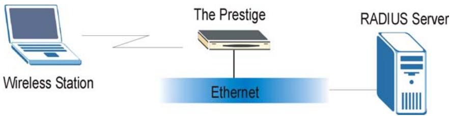
flowchart
graph LR
    A["Wireless Station"] --> B["The Prestige"]
    B --> C["Ethernet"]
    C --> D["RADIUS Server"]
Figure 5-5 EAP Authentication
The details below provide a general description of how IEEE 802.1x EAP authentication works. For an example list of EAP-MD5 authentication steps, see the IEEE 802.1x appendix.
Step 1. The wireless station sends a “start” message to the Prestige.
Step 2. The Prestige sends a “request identity” message to the wireless station for identity information.
Step 3. The wireless station replies with identity information, including username and password.
Step 4. The RADIUS server checks the user information against its user profile database and determines whether or not to authenticate the wireless station.
5.9 Configuring 802.1x
To change your Prestige's authentication settings, click Wireless LAN, 802.1x. The screen appears as shown.
Wireless LAN - 802.1x
802.1x Authentication
Wireless Port Control
ReAuthentication Timer
Idle Timeout
Authentication Databases
No Authentication Required
1800
(In Seconds)
3600
(In Seconds)
Local User Database Only
Back
Apply
Cancel
Figure 5-6 802.1x
The following table describes the labels in this screen.
Table 5-3 802.1x
| LABEL | DESCRIPTION |
| Wireless Port Control | To control wireless stations access to the wired network, select a control method from the drop-down list box. Choose fromNo Authentication Required, Authentication Requiredand No Access Allowed.No Authentication Requiredallows all wireless stations access to the wired network without entering user names and passwords. This is the default setting.Authentication Requiredmeans that all wireless stations have to enter user names and passwords before access to the wired network is allowed.No Access Allowedblocks all wireless stations access to the wired network. |
| ReAuthentication Timer | Specify how often wireless stations have to re-enter user names and passwords in order to stay connected. This field is activated only when you selectAuthentication Requiredin the Wireless Port Controlfield.Enter a time interval between 10 and 9999 seconds. The default time interval is1800 seconds (30 minutes).If wireless station authentication is done using a RADIUS server, the reauthentication timer on the RADIUS server has priority. |
| Idle Timeout | The Prestige automatically disconnects a wireless station from the wired network after a period of inactivity. The wireless station needs to enter the user name and password again before access to the wired network is allowed.This field is activated only when you selectAuthentication Requiredin the Wireless Port Controlfield. The default time interval is3600seconds (1 hour). |
Table 5-3 802.1x
| LABEL | DESCRIPTION |
| Authentication Databases | This field is activated only when you select Authentication Required in the Wireless Port Control field.The authentication database contains wireless station login information. The local user database is the built-in database on the Prestige. The RADIUS is an external server. Use this drop-down list box to select which database the Prestige should use (first) to authenticate a wireless station.Before you specify the priority, make sure you have set up the corresponding database(s) correctly.Select Local User Database Only to have the Prestige just check the built-in user database on the Prestige for a wireless station's user name and password.Select RADIUS Only to have the Prestige just check the user database on the specified RADIUS server for a wireless station's user name and password.Select Local first, then RADIUS to have the Prestige first check the user database on the Prestige for a wireless station's user name and password. If the user name is not found, the Prestige checks the user database on the specified RADIUS server.Select RADIUS first, then Local to have the Prestige first check the user database on the specified RADIUS server for a wireless station's user name and password. When the user name is not found or password does not match in the RADIUS server, the Prestige will not check the local user database and the authentication fails. If the Prestige cannot reach the RADIUS server, then the Prestige checks the local user database on the Prestige. |
| Back | Click Back to go to the main wireless LAN setup screen. |
| Apply | Click Apply to save these settings back to the Prestige. |
| Cancel | Click Cancel to begin configuring this screen again. |
5.10 Configuring Local User Authentication
By storing user profiles locally, your Prestige is able to authenticate wireless users without interacting with a network RADIUS server. However, there is a limit on the number of users you may authenticate in this way.
To change your Prestige's local user database, click Wireless LAN, Local User Database. The screen appears as shown.
Wireless LAN · Local User DataBase
| # | Active | User Name | Password |
| 1 | |||
| 2 | |||
| 3 | |||
| 4 | |||
| 5 | |||
| 6 | |||
| 7 | |||
| 8 | |||
| 9 | |||
| 10 | |||
| 11 | |||
| 12 | |||
| 13 | |||
| 14 | |||
| 15 | |||
| 16 | |||
| 17 | |||
| 18 | |||
| 19 | |||
| 20 | |||
| 21 | |||
| 22 | |||
| 23 | |||
| 24 | |||
| 25 | |||
| 26 | |||
| 27 | |||
| 28 | |||
| 29 | |||
| 30 | |||
| 31 | |||
| 32 |
Back
Apply
Cancel
Figure 5-7 Local User Database
The following table describes the labels in this screen.
Table 5-4 Local User Database
| LABEL | DESCRIPTION |
| # | This is the index number of a local user account. |
| Active | Select this check box to enable the user profile. |
| User Name | Enter the user name of the user profile. |
| Password | Enter a password up to 31 characters long for this user profile. |
| Back | Click Back to go to the main wireless LAN setup screen. |
| Apply | Click Apply to save these settings back to the Prestige. |
| Cancel | Click Cancel to begin configuring this screen again. |
5.11 Configuring RADIUS
Once you enable the EAP authentication, you need to specify the external sever for remote user authentication and accounting.
To set up your Prestige's RADIUS server settings, click WIRELESS LAN, RADIUS. The screen appears as shown.
Wireless LAN · Radius
Authentication Server
Active

Server IP Address

Port Number
Shared Secret
Accounting Server
Active

Server IP Address

Port Number
Shared Secret
Back
Apply
Cancel
Figure 5-8 RADIUS
The following table describes the labels in this screen.
Table 5-5 RADIUS
| LABEL | DESCRIPTION |
| Authentication Server | |
| Active | Select Yes from the drop-down list box to enable user authentication through an external authentication server. |
| Server IP Address | Enter the IP address of the external authentication server in dotted decimal notation. |
Table 5-5 RADIUS
| LABEL | DESCRIPTION |
| Port Number | The default port of the RADIUS server for authentication is 1812.You need not change this value unless your network administrator instructs you to do so with additional information. |
| Shared Secret | Enter a password (up to 31 alphanumeric characters) as the key to be shared between the external authentication server and the access points.The key is not sent over the network. This key must be the same on the external authentication server and Prestige. |
| Accounting Server | |
| Active | Select Yes from the drop-down list box to enable user authentication through an external accounting server. |
| Server IP Address | Enter the IP address of the external accounting server in dotted decimal notation. |
| Port Number | The default port of the RADIUS server for accounting is 1813.You need not change this value unless your network administrator instructs you to do so with additional information. |
| Shared Secret | Enter a password (up to 31 alphanumeric characters) as the key to be shared between the external accounting server and the access points.The key is not sent over the network. This key must be the same on the external accounting server and the Prestige. |
| Back | Click Back to go to the main wireless LAN setup screen. |
| Apply | Click Apply to save these settings back to the Prestige. |
| Cancel | Click Cancel to begin configuring this screen again. |
Chapter 6
WAN Setup
This chapter describes how to configure WAN settings.
6.1 WAN Overview
A WAN (Wide Area Network) is an outside connection to another network or the Internet.
See the Wizard Setup chapter for more information on the fields in the WAN screens.
6.2 PPPoE Encapsulation
The Prestige supports PPPoE (Point-to-Point Protocol over Ethernet). PPPoE is an IETF Draft standard (RFC 2516) specifying how a personal computer (PC) interacts with a broadband modem (DSL, cable, wireless, etc.) connection. The PPPoE option is for a dial-up connection using PPPoE.
For the service provider, PPPoE offers an access and authentication method that works with existing access control systems (for example Radius). PPPoE provides a login and authentication method that the existing Microsoft Dial-Up Networking software can activate, and therefore requires no new learning or procedures for Windows users.
One of the benefits of PPPoE is the ability to let you access one of multiple network services, a function known as dynamic service selection. This enables the service provider to easily create and offer new IP services for individuals.
Operationally, PPPoE saves significant effort for both you and the ISP or carrier, as it requires no specific configuration of the broadband modem at the customer site.
By implementing PPPoE directly on the Prestige (rather than individual computers), the computers on the LAN do not need PPPoE software installed, since the Prestige does that part of the task. Furthermore, with NAT, all of the LANs' computers will have access.
6.3 PPTP Encapsulation
Point-to-Point Tunneling Protocol (PPTP) is a network protocol that enables secure transfer of data from a remote client to a private server, creating a Virtual Private Network (VPN) using TCP/IP-based networks.
PPTP supports on-demand, multi-protocol and virtual private networking over public networks, such as the Internet.
6.4 Traffic Shaping
Traffic Shaping is an agreement between the carrier and the subscriber to regulate the average rate and “burstiness” or fluctuation of data transmission over an ATM network. This agreement helps eliminate congestion, which is important for transmission of real time data such as audio and video connections.
Peak Cell Rate (PCR) is the maximum rate at which the sender can send cells. This parameter may be lower (but not higher) than the maximum line speed. 1 ATM cell is 53 bytes (424 bits), so a maximum speed of 832 Kbps gives a maximum PCR of 1962 cells/sec. This rate is not guaranteed because it is dependent on the line speed.
Sustained Cell Rate (SCR) is the mean cell rate of a bursty, on-off traffic source that can be sent at the peak rate, and a parameter for burst-type traffic. SCR may not be greater than the PCR; the system default is 0 cells/sec.
Maximum Burst Size (MBS) is the maximum number of cells that can be sent at the PCR. After MBS is reached, cell rates fall below SCR until cell rate averages to the SCR again. At this time, more cells (up to the MBS) can be sent at the PCR again.
If the PCR, SCR or MBS is set to the default of “0”, the system will assign a maximum value that correlates to your upstream line rate.
The following figure illustrates the relationship between PCR, SCR and MBS.
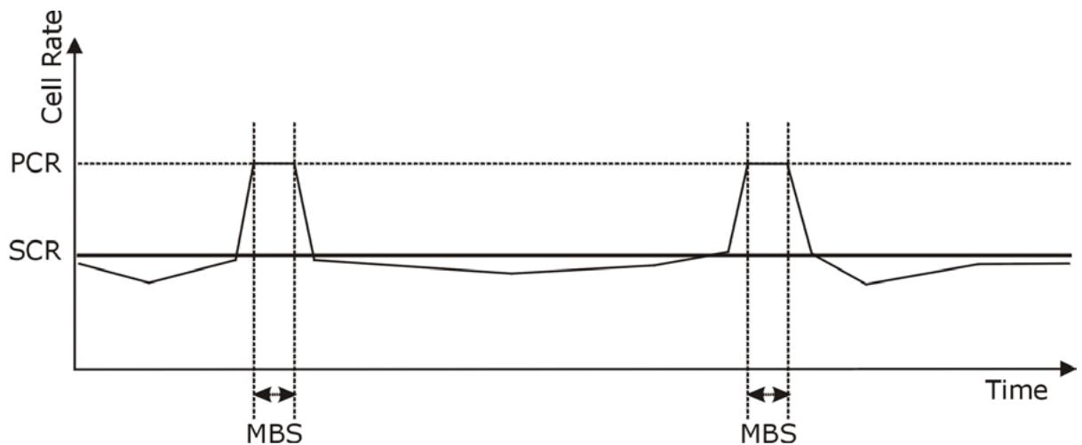
line
| Time Point | Cell Rate | | ---------- | --------- | | MBS | PCR | | MBS | SCR |Figure 6-1 Example of Traffic Shaping
6.5 Configuring WAN Setup
To change your Prestige's WAN remote node settings, click WAN. The screen differs by the encapsulation.
Internet Access Setup
Name
MyISP
Mode
Routing
Encapsulation
PPPoE
Multiplex
LLC
Virtual Circuit ID
VPI
8
VCI
35
ATM QoS Type
UBR
Cell Rate
Peak Cell Rate
0 cell/sec
Sustain Cell Rate
0 cell/sec
Maximum Burst Size
0
Login Information
Service Name
The image contains no text. The horizontal line is a stylistic or background element and must be ignored according to the rules.
User Name
user@isp.ch
Password
:
IP Address
Obtain an IP Address Automatically
Static IP Address
IP Address
0.0.0.0
Connection
○ Nailed-Up Connection
Connect on Demand
Max Idle Timeout
1500 sec

Figure 6-2 Internet Access Setup
The following table describes the labels in this screen.
Table 6-1 Internet Access Setup
| LABEL | DESCRIPTION |
| Name | Enter the name of your Internet Service Provider, e.g., MyISP. This information is for identification purposes only. |
| Mode | SelectRouting(default) from the drop-down list box if your ISP allows multiple computers to share an Internet account. Otherwise selectBridge. |
| Encapsulation | Select the method of encapsulation used by your ISP from the drop-down list box.Choices vary depending on the mode you select in theModefield.If you selectBridgein theModefield, select either PPPoA or RFC 1483.If you selectRoutingin theModefield, select PPPoA, RFC 1483, ENET ENCAP or PPPoE. |
| Multiplex | Select the method of multiplexing used by your ISP from the drop-down list. Choices areVCorLLC. |
| Virtual Circuit ID | VPI (Virtual Path Identifier) and VCI (Virtual Channel Identifier) define a virtual circuit.Refer to the appendix for more information. |
| VPI | The valid range for the VPI is 0 to 255. Enter the VPI assigned to you. |
| VCI | The valid range for the VCI is 32 to 65535 (0 to 31 is reserved for local management of ATM traffic). Enter the VCI assigned to you. |
| ATM QoS Type | SelectCBR(Continuous Bit Rate) to specify fixed (always-on) bandwidth for voice or data traffic. SelectUBR(Unspecified Bit Rate) for applications that are non-time sensitive, such as e-mail. SelectVBR(Variable Bit Rate) for bursty traffic and bandwidth sharing with other applications.VBRis not available on all models. |
| Cell Rate | Cell rate configuration often helps eliminate traffic congestion that slows transmission of real time data such as audio and video connections. |
| Peak Cell Rate | Divide the DSL line rate (bps) by 424 (the size of an ATM cell) to find the Peak Cell Rate (PCR). This is the maximum rate at which the sender can send cells. Type the PCR here. |
| Sustain Cell Rate | The Sustain Cell Rate (SCR) sets the average cell rate (long-term) that can be transmitted. Type the SCR, which must be less than the PCR. |
Table 6-1 Internet Access Setup
| LABEL | DESCRIPTION |
| Maximum Burst Size | Maximum Burst Size (MBS) refers to the maximum number of cells that can be sent at the peak rate. Type the MBS, which is less than 65535. |
| Login Information | (PPPoA and PPPoE encapsulation only) |
| Service Name | (PPPoE only) Type the name of your PPPoE service here. |
| User Name | Enter the user name exactly as your ISP assigned. If assigned a name in the formuser@domainwhere domain identifies a service name, then enter both components exactly as given. |
| Password | Enter the password associated with the user name above. |
| IP Address | A static IP address is a fixed IP that your ISP gives you. A dynamic IP address is not fixed; the ISP assigns you a different one each time you connect to the Internet. The Single User Account feature can be used with either a dynamic or static IP address.SelectObtain an IP Address Automaticallyif you have a dynamic IP address; otherwise selectStatic IP Addressand type your ISP assigned IP address in theIPAddressfield below. |
| Connection (PPPoA and PPPoE encapsulation only) | The schedule rule(s) in SMT menu 26 have priority over yourConnectionsettings. |
| Nailed-Up Connection | SelectNailed-Up Connectionwhen you want your connection up all the time. The Prestige will try to bring up the connection automatically if it is disconnected. |
| Connect on Demand | SelectConnect on Demandwhen you don't want the connection up all the time and specify an idle time-out in theMax Idle Timeoutfield. |
| Max Idle Timeout | Specify an idle time-out in theMax Idle Timeoutfield when you selectConnect on Demand. The default setting is 0, which means the Internet session will not timeout. |
| Subnet Mask (ENET ENCAP encapsulation only) | Enter a subnet mask in dotted decimal notation.Refer to the Subnettingappendix in the to calculate a subnet mask If you are implementing subnetting. |
Table 6-1 Internet Access Setup
| LABEL | DESCRIPTION |
| ENET ENCAP Gateway (ENET ENCAP encapsulation only) | You must specify a gateway IP address (supplied by your ISP) when you select ENET ENCAP in the Encapsulation field. |
| Back | Click Back to return to the previous screen. |
| Apply | Click Apply to save the changes. |
| Cancel | Click Cancel to begin configuring this screen afresh. |
Part III:
NAT, Dynamic DNS and Time Zone
This part covers NAT (Network Address Translation), dynamic DNS (Domain Name Sever) and Time Zone setup.
Chapter 7
Network Address Translation (NAT)
This chapter discusses how to configure NAT on the Prestige.
7.1 NAT Overview
NAT (Network Address Translation - NAT, RFC 1631) is the translation of the IP address of a host in a packet, for example, the source address of an outgoing packet, used within one network to a different IP address known within another network.
7.1.1 NAT Definitions
Inside/outside denotes where a host is located relative to the Prestige, for example, the computers of your subscribers are the inside hosts, while the web servers on the Internet are the outside hosts.
Global/local denotes the IP address of a host in a packet as the packet traverses a router, for example, the local address refers to the IP address of a host when the packet is in the local network, while the global address refers to the IP address of the host when the same packet is traveling in the WAN side.
Note that inside/outside refers to the location of a host, while global/local refers to the IP address of a host used in a packet. Thus, an inside local address (ILA) is the IP address of an inside host in a packet when the packet is still in the local network, while an inside global address (IGA) is the IP address of the same inside host when the packet is on the WAN side. The following table summarizes this information.
Table 7-1 NAT Definitions
| ITEM | DESCRIPTION |
| Inside | This refers to the host on the LAN. |
| Outside | This refers to the host on the WAN. |
| Local | This refers to the packet address (source or destination) as the packet travels on the LAN. |
| Global | This refers to the packet address (source or destination) as the packet travels on the WAN. |
NAT never changes the IP address (either local or global) of an outside host.
7.1.2 What NAT Does
In the simplest form, NAT changes the source IP address in a packet received from a subscriber (the inside local address) to another (the inside global address) before forwarding the packet to the WAN side. When the response comes back, NAT translates the destination address (the inside global address) back to the inside
local address before forwarding it to the original inside host. Note that the IP address (either local or global) of an outside host is never changed.
The global IP addresses for the inside hosts can be either static or dynamically assigned by the ISP. In addition, you can designate servers, for example, a web server and a telnet server, on your local network and make them accessible to the outside world. With no servers defined, your Prestige filters out all incoming inquiries, thus preventing intruders from probing your network. For more information on IP address translation, refer to RFC 1631, The IP Network Address Translator (NAT).
7.1.3 How NAT Works
Each packet has two addresses – a source address and a destination address. For outgoing packets, the ILA (Inside Local Address) is the source address on the LAN, and the IGA (Inside Global Address) is the source address on the WAN. For incoming packets, the ILA is the destination address on the LAN, and the IGA is the destination address on the WAN. NAT maps private (local) IP addresses to globally unique ones required for communication with hosts on other networks. It replaces the original IP source address (and TCP or UDP source port numbers for Many-to-One and Many-to-Many Overload NAT mapping) in each packet and then forwards it to the Internet. The Prestige keeps track of the original addresses and port numbers so incoming reply packets can have their original values restored. The following figure illustrates this.
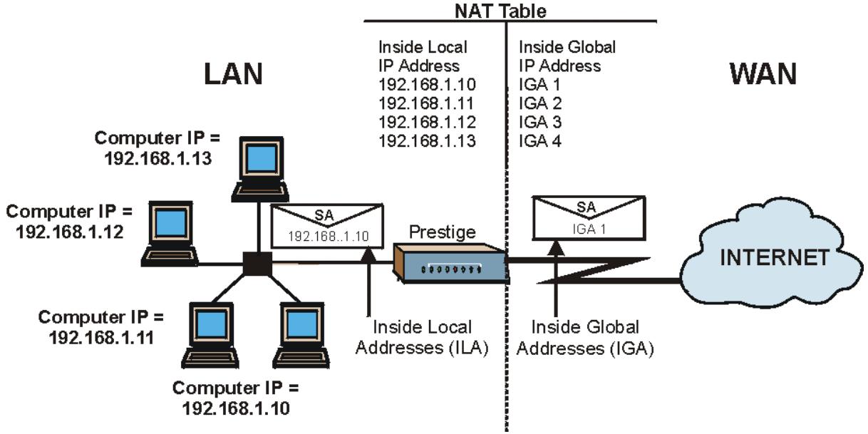
flowchart
graph TD
    subgraph LAN
        A["Computer IP = 192.168.1.13"] --> B["SA 192.168..1.10"]
        C["Computer IP = 192.168.1.12"] --> B
        D["Computer IP = 192.168.1.11"] --> B
        E["Computer IP = 192.168.1.10"] --> B
    end
    subgraph WAN
        F["SA IGA 1"] --> G["Internet"]
        H["Inside Global IP Address IGA 1"] --> G
        I["Inside Global IP Address IGA 2"] --> G
        J["Inside Global IP Address IGA 3"] --> G
        K["Inside Global IP Address IGA 4"] --> G
    end
    B --> L["Prestige"]
    B --> L
    L --> G
    style LAN fill:#f9f,stroke:#333
    style WAN fill:#bbf,stroke:#333
Figure 7-1 How NAT Works
7.1.4 NAT Application
The following figure illustrates a possible NAT application, where three inside LANs (logical LANs using IP Alias) behind the Prestige can communicate with three distinct WAN networks. More examples follow at the end of this chapter.
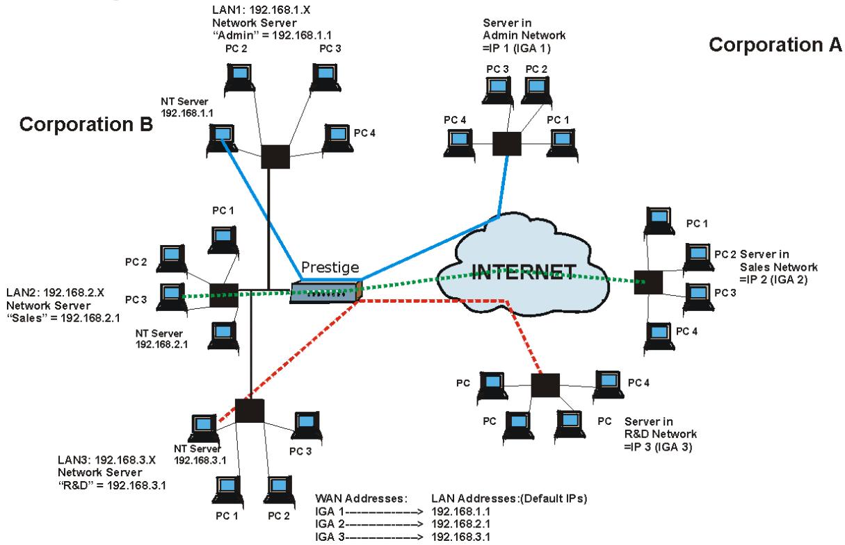
flowchart
Network architecture diagram showing interconnection between Corporation B and Internet with Prestige, Network Server, and Server in Admin/Sales/RI&D networks.Figure 7-2 NAT Application With IP Alias
7.1.5 NAT Mapping Types
NAT supports five types of IP/port mapping. They are:
- One to One: In One-to-One mode, the Prestige maps one local IP address to one global IP address.
- Many to One: In Many-to-One mode, the Prestige maps multiple local IP addresses to one global IP address. This is equivalent to SUA (for instance, PAT, port address translation), ZyXEL's Single User Account feature that previous ZyXEL routers supported (the SUA Only option in today's routers).
-
Many to Many Overload: In Many-to-Many Overload mode, the Prestige maps the multiple local IP addresses to shared global IP addresses.
-
Many-to-Many No Overload: In Many-to-Many No Overload mode, the Prestige maps each local IP address to a unique global IP address.
- Server: This type allows you to specify inside servers of different services behind the NAT to be accessible to the outside world.
Port numbers do not change for One-to-One and Many-to-Many No Overload NAT mapping types.
The following table summarizes these types.
Table 7-2 NAT Mapping Types
| TYPE | IP MAPPING | SMT ABBREVIATION |
| One-to-One | ILA1←→ IGA1 | 1:1 |
| Many-to-One (SUA/PAT) | ILA1←→ IGA1ILA2←→ IGA1... | M:1 |
| Many-to-Many Overload | ILA1←→ IGA1ILA2←→ IGA2ILA3←→ IGA1ILA4←→ IGA2... | M:M Ov |
| Many-to-Many No Overload | ILA1←→ IGA1ILA2←→ IGA2ILA3←→ IGA3... | M:M No OV |
| Server | Server 1 IP←→ IGA1Server 2 IP←→ IGA1Server 3 IP←→ IGA1 | Server |
7.2 SUA (Single User Account) Versus NAT
SUA (Single User Account) is a ZyNOS implementation of a subset of NAT that supports two types of mapping, Many-to-One and Server. The Prestige also supports Full Feature NAT to map multiple global IP addresses to multiple private LAN IP addresses of clients or servers using mapping types as outlined in Table 7-2.
- Choose SUA Only if you have just one public WAN IP address for your Prestige.
- Choose Full Feature if you have multiple public WAN IP addresses for your Prestige.
7.3 SUA Server
A SUA server set is a list of inside (behind NAT on the LAN) servers, for example, web or FTP, that you can make visible to the outside world even though SUA makes your whole inside network appear as a single computer to the outside world.
You may enter a single port number or a range of port numbers to be forwarded, and the local IP address of the desired server. The port number identifies a service; for example, web service is on port 80 and FTP on port 21. In some cases, such as for unknown services or where one server can support more than one service (for example both FTP and web service), it might be better to specify a range of port numbers. You can allocate a server IP address that corresponds to a port or a range of ports.
Many residential broadband ISP accounts do not allow you to run any server processes (such as a Web or FTP server) from your location. Your ISP may periodically check for servers and may suspend your account if it discovers any active services at your location. If you are unsure, refer to your ISP.
Default Server IP Address
In addition to the servers for specified services, NAT supports a default server IP address. A default server receives packets from ports that are not specified in this screen.
If you do not assign a Default Server IP Address, then all packets received for ports not specified in this screen will be discarded.
7.3.1 Port Forwarding: Services and Port Numbers
A NAT server set is a list of inside (behind NAT on the LAN) servers, for example, web or FTP, that you can make accessible to the outside world even though NAT makes your whole inside network appear as a single machine to the outside world.
Use the SUA Server page to forward incoming service requests to the server(s) on your local network. You may enter a single port number or a range of port numbers to be forwarded, and the local IP address of the desired server. The port number identifies a service; for example, web service is on port 80 and FTP on port 21. In some cases, such as for unknown services or where one server can support more than one service (for example both FTP and web service), it might be better to specify a range of port numbers.
In addition to the servers for specified services, NAT supports a default server. A service request that does not have a server explicitly designated for it is forwarded to the default server. If the default is not defined, the service request is simply discarded.
Many residential broadband ISP accounts do not allow you to run any server processes (such as a Web or FTP server) from your location. Your ISP may periodically check for servers and may suspend your account if it discovers any active services at your location. If you are unsure, refer to your ISP.
The most often used port numbers are shown in the following table. Please refer to RFC 1700 for further information about port numbers.
Table 7-3 Services and Port Numbers
| SERVICES | PORT NUMBER |
| ECHO | 7 |
| FTP (File Transfer Protocol) | 21 |
| SMTP (Simple Mail Transfer Protocol) | 25 |
| DNS (Domain Name System) | 53 |
| Finger | 79 |
| HTTP (Hyper Text Transfer protocol or WWW, Web) | 80 |
| POP3 (Post Office Protocol) | 110 |
| NNTP (Network News Transport Protocol) | 119 |
| SNMP (Simple Network Management Protocol) | 161 |
| SNMP trap | 162 |
| PPTP (Point-to-Point Tunneling Protocol) | 1723 |
7.3.2 Configuring Servers Behind SUA (Example)
Let's say you want to assign ports 22-25 to one server, port 80 to another and assign a default server IP address of 192.168.1.35 as shown in the next figure.
The NAT network appears as a single host on the Internet
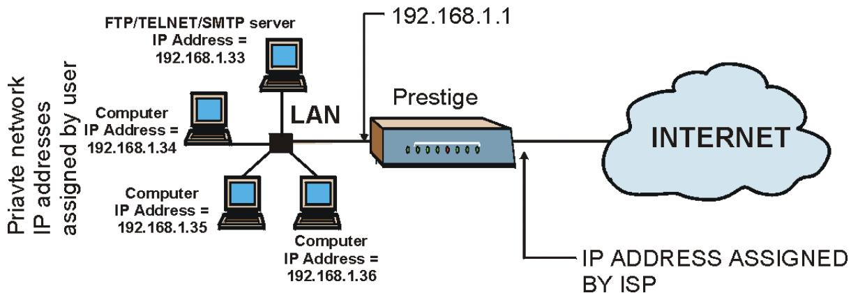
flowchart
graph TD
    A["Internet"] -->|IP ADDRESS ASSIGNED BY ISP| B["Prestige"]
    B --> C["LAN"]
    C --> D["Computer IP Address = 192.168.1.34"]
    C --> E["Computer IP Address = 192.168.1.35"]
    C --> F["Computer IP Address = 192.168.1.36"]
    G["FTP/TELNET/SMTP server"] --> H["IP Address = 192.168.1.33"]
    G --> I["192.168.1.1"]
    style G fill:#cce5ff,stroke:#333
Figure 7-3 Multiple Servers Behind NAT Example
7.4 Selecting the NAT Mode
Click NAT to open the following screen.
NAT·Mode
Network Address Translation
○ None
● SUA Only
Edit Details
Full Feature
Edit Details
Apply
Figure 7-4 NAT Mode
The following table describes the labels in this screen.
Table 7-4 NAT Mode
| LABEL | DESCRIPTION |
| None | Select this radio button to disable NAT. |
| SUA Only | Select this radio button if you have just one public WAN IP address for your Prestige. The Prestige uses Address Mapping Set 1 in the NAT - Edit SUA/NAT Server Set screen. |
| Edit Details | Click this link to go to the NAT - Edit SUA/NAT Server Set screen. |
| Full Feature | Select this radio button if you have multiple public WAN IP addresses for your Prestige. |
| Edit Details | Click this link to go to the NAT - Address Mapping Rules screen. |
| Apply | Click Apply to save your configuration. |
7.5 Configuring SUA Server
If you do not assign an IP Address in Server Set 1 (default server), then all packets received for ports not specified in this screen will be discarded.
Click NAT, Select SUA Only and click Edit Details to open the following screen.
NAT · Edit SUA/NAT Server Set
| Start Port No. | End Port No. | IP Address | |
| 1 | All ports | All ports | 0.0.0.0 |
| 2 | 0 | 0 | 0.0.0.0 |
| 3 | 0 | 0 | 0.0.0.0 |
| 4 | 0 | 0 | 0.0.0.0 |
| 5 | 0 | 0 | 0.0.0.0 |
| 6 | 0 | 0 | 0.0.0.0 |
| 7 | 0 | 0 | 0.0.0.0 |
| 8 | 0 | 0 | 0.0.0.0 |
| 9 | 0 | 0 | 0.0.0.0 |
| 10 | 0 | 0 | 0.0.0.0 |
| 11 | 0 | 0 | 0.0.0.0 |
| 12 | 0 | 0 | 0.0.0.0 |

Cancel
Figure 7-5 Edit SUA/NAT Server Set
The following table describes the labels in this screen.
Table 7-5 Edit SUA/NAT Server Set
| LABEL | DESCRIPTION |
| Start Port No. | Enter a port number in this field.To forward only one port, enter the port number again in the End Port No. field.To forward a series of ports, enter the start port number here and the end port number in the End Port No. field. |
Table 7-5 Edit SUA/NAT Server Set
| LABEL | DESCRIPTION |
| End Port No. | Enter a port number in this field.To forward only one port, enter the port number again in the Start Port No. field above and then enter it again in this field.To forward a series of ports, enter the last port number in a series that begins with the port number in the Start Port No. field above. |
| IP Address | Enter your server IP address in this field. |
| Save | Click Save to save your changes back to the Prestige. |
| Cancel | Click Cancel to return to the previous configuration. |
7.6 Configuring Address Mapping
Ordering your rules is important because the Prestige applies the rules in the order that you specify. When a rule matches the current packet, the Prestige takes the corresponding action and the remaining rules are ignored. If there are any empty rules before your new configured rule, your configured rule will be pushed up by that number of empty rules. For example, if you have already configured rules 1 to 6 in your current set and now you configure rule number 9. In the set summary screen, the new rule will be rule 7, not 9. Now if you delete rule 4, rules 5 to 7 will be pushed up by 1 rule, so old rules 5, 6 and 7 become new rules 4, 5 and 6.
To change your Prestige's address mapping settings, click NAT, Select Full Feature and click Edit Details to open the following screen.
NAT · Address Mapping Rules
| Local Start IP | Local End IP | Global Start IP | Global End IP | Type | |
| Rule 1 | ... | ... | ... | ... | - |
| Rule 2 | ... | ... | ... | ... | - |
| Rule 3 | ... | ... | ... | ... | - |
| Rule 4 | ... | ... | ... | ... | - |
| Rule 5 | ... | ... | ... | ... | - |
| Rule 6 | ... | ... | ... | ... | - |
| Rule 7 | ... | ... | ... | ... | - |
| Rule 8 | ... | ... | ... | ... | - |
| Rule 9 | ... | ... | ... | ... | - |
| Rule 10 | ... | ... | ... | ... | - |
Back
Figure 7-6 Address Mapping Rules
The following table describes the labels in this screen.
Table 7-6 Address Mapping Rules
| LABEL | DESCRIPTION |
| Local Start IP | This is the starting Inside Local IP Address (ILA). Local IP addresses are N/A for Server port mapping. |
| Local End IP | This is the end Inside Local IP Address (ILA). If your rule is for all local IP addresses, then enter 0.0.0.0 as the Local Start IP address and 255.255.255.255 as the Local End IP address. This field is N/A for One-to-one and Server mapping types. |
| Global Start IP | This is the starting Inside Global IP Address (IGA). Enter 0.0.0.0 here if you have a dynamic IP address from your ISP. You can only do this for Many-to-One and Server mapping types. |
| Global End IP | This is the ending Inside Global IP Address (IGA). This field is N/A for One-to-one, Many-to-One and Server mapping types. |
Table 7-6 Address Mapping Rules
| LABEL | DESCRIPTION |
| Type | 1-1: One-to-one mode maps one local IP address to one global IP address. Note that port numbers do not change for the One-to-one NAT mapping type.M-1: Many-to-One mode maps multiple local IP addresses to one global IP address. This is equivalent to SUA (i.e., PAT, port address translation), ZyXEL's Single User Account feature that previous ZyXEL routers supported only.M-M Ov (Overload): Many-to-Many Overload mode maps multiple local IP addresses to shared global IP addresses.MM No (No Overload): Many-to-Many No Overload mode maps each local IP address to unique global IP addresses.Server: This type allows you to specify inside servers of different services behind the NAT to be accessible to the outside world. |
| Back | Click Back to return to the NAT Mode screen. |
7.7 Editing an Address Mapping Rule
To edit an address mapping rule, click the rule's link in the NAT Address Mapping Rules screen to display the screen shown next.
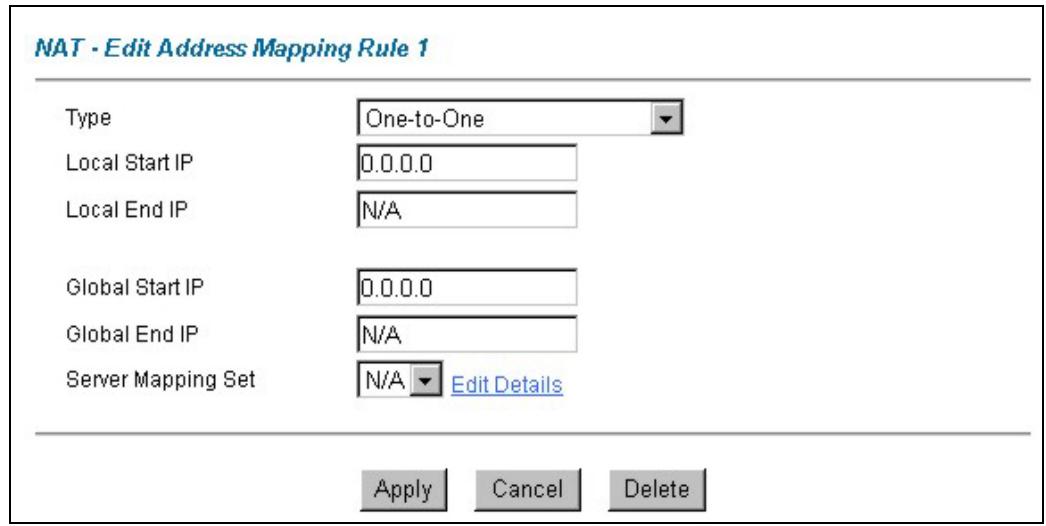
text_image
NAT - Edit Address Mapping Rule 1 Type One-to-One Local Start IP 0.0.0.0 Local End IP N/A Global Start IP 0.0.0.0 Global End IP N/A Server Mapping Set N/A Edit Details Apply Cancel DeleteFigure 7-7 Address Mapping Rule Edit
The following table describes the labels in this screen.
Table 7-7 Address Mapping Rule Edit
| LABEL | DESCRIPTION |
| Type | Choose the port mapping type from one of the following.1.One-to-One: One-to-One mode maps one local IP address to one global IP address. Note that port numbers do not change for One-to-one NAT mapping type.2.Many-to-One: Many-to-One mode maps multiple local IP addresses to one global IP address. This is equivalent to SUA (i.e., PAT, port address translation), ZyXEL's Single User Account feature that previous ZyXEL routers supported only.3.Many-to-Many Overload: Many-to-Many Overload mode maps multiple local IP addresses to shared global IP addresses.4.Many-to-Many No Overload: Many-to-Many No Overload mode maps each local IP address to unique global IP addresses.5.Server: This type allows you to specify inside servers of different services behind the NAT to be accessible to the outside world. |
| Local Start IP | This is the starting local IP address (ILA). Local IP addresses are N/A for Server port mapping. |
| Local End IP | This is the end local IP address (ILA). If your rule is for all local IP addresses, then enter 0.0.0.0 as the Local Start IP address and 255.255.255.255 as the Local End IP address.This field is N/A for One-to-One and Server mapping types. |
| Global Start IP | This is the starting global IP address (IGA). Enter 0.0.0.0 here if you have a dynamic IP address from your ISP. |
| Global End IP | This is the ending global IP address (IGA). This field is N/A for One-to-One, Many-to-One and Server mapping types. |
| Server Mapping Set | Only available when Type is set to Server.Select a number from 1 to 10 from the drop-down menu to choose a server set from the NAT - Address Mapping Rules screen. |
| Edit Details | Click this link to go to the NAT - Edit SUA/NAT Server Set screen to edit a server set that you have selected in the Server Mapping Set field. |
| Apply | Click Apply to save your changes back to the Prestige. |
| Cancel | Click Cancel to return to the previously saved settings. |
| Delete | Click Delete to exit this screen without saving |
Chapter 8
Dynamic DNS Setup
This chapter discusses how to configure your Prestige to use Dynamic DNS.
8.1 Dynamic DNS
Dynamic DNS allows you to update your current dynamic IP address with one or many dynamic DNS services so that anyone can contact you (in NetMeeting, CU-SeeMe, etc.). You can also access your FTP server or Web site on your own computer using a DNS-like address (for instance myhost.dhs.org, where myhost is a name of your choice) that will never change instead of using an IP address that changes each time you reconnect. Your friends or relatives will always be able to call you even if they don't know your IP address.
First of all, you need to have registered a dynamic DNS account with www.dyndns.org. This is for people with a dynamic IP from their ISP or DHCP server that would still like to have a DNS name. The Dynamic DNS service provider will give you a password or key.
8.1.1 DYNDNS Wildcard
Enabling the wildcard feature for your host causes *.yourhost.dyndns.org to be aliased to the same IP address as yourhost.dyndns.org. This feature is useful if you want to be able to use, for example, www.yourhost.dyndns.org and still reach your hostname.
If you have a private WAN IP address, then you cannot use Dynamic DNS.
8.2 Configuring Dynamic DNS
To change your Prestige's DDNS, click Dynamic DNS. The screen appears as shown.
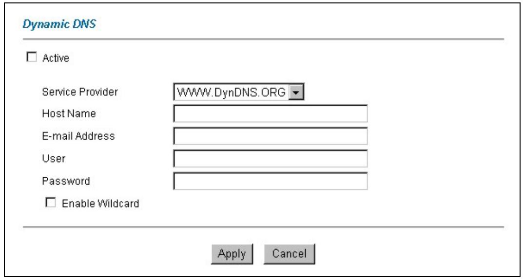
text_image
Dynamic DNS Active Service Provider WWW.DynDNS.ORG Host Name E-mail Address User Password Enable Wildcard Apply CancelFigure 8-1 DDNS
The following table describes the labels in this screen.
Table 8-1 DDNS
| LABEL | DESCRIPTION |
| Active | Select this check box to use dynamic DNS. |
| Service Provider | Select the name of your Dynamic DNS service provider. |
| Host Name | Type the domain name assigned to your Prestige by your Dynamic DNS provider. |
| E-mail Address | Type your e-mail address. |
| User | Type your user name. |
| Password | Type the password assigned to you. |
| Enable Wildcard | Select this check box to enable DYNDNS Wildcard. |
| Apply | Click Apply to save your changes back to the Prestige. |
| Cancel | Click Cancel to return to the previously saved settings. |
Chapter 9
Time and Date Setup
Use this screen to configure the Prestige's time and date settings. This chapter is not available on all models.
9.1 Configuring Time Zone
To change your Prestige's time and date, click Time Zone. The screen appears as shown. Use this screen to configure the Prestige's time based on your local time zone.
Time Zone
Time Server
Use Time Server when Bootup

Time Server IP Address
Time Zone
(GMT) Greenwich Mean Time : Dublin, Edinburgh, Lisbon, London
□ Daylight Saving
Start Date
End Date
□ Calibrate system clock with Time Server now.
(Attention! This may take up to 60 seconds if Time Server is unreachable).
Date
Current Date
New Date (yyyy-mm-dd)
Time
Current Time
New Time

Figure 9-1 Time/Date
The following table describes the labels in this screen.
Table 9-1 Time/Date
| LABEL | DESCRIPTION |
| Time Server | |
| Use Time Server when Bootup | Select the time service protocol that your time server sends when you turn on the Prestige. Not all time servers support all protocols, so you may have to check with your ISP/network administrator or use trial and error to find a protocol that works.The main difference between them is the format.Daytime (RFC 867) format is day/month/year/time zone of the server.Time (RFC 868) format displays a 4-byte integer giving the total number of seconds since 1970/1/1 at 0:0:0.The default, NTP (RFC 1305), is similar to Time (RFC 868).Select None to enter the time and date manually. |
| Time Server IP Address | Enter the IP address of your time server. Check with your ISP/network administrator if you are unsure of this information. |
| Time Zone | Choose the time zone of your location. This will set the time difference between your time zone and Greenwich Mean Time (GMT). |
| Daylight Savings | Select this option if you use daylight savings time. Daylight saving is a period from late spring to early fall when many countries set their clocks ahead of normal local time by one hour to give more daytime light in the evening. |
| Start Date | Enter the month and day that your daylight-savings time starts on if you selected Daylight Savings. |
| End Date | Enter the month and day that your daylight-savings time ends on if you selected Daylight Savings. |
| Calibrate system clock with Time Server now | Click this button to have your Prestige use the time server (that you configured above) to set its internal system clock.Please wait for up to 60 seconds while the Prestige locates the time server. If the Prestige cannot find the time server, please check the time server protocol and its IP address. If the IP address was entered correctly, try pinging it for example to test the connection. |
| Date | |
| Current Date | This field displays the date of your Prestige.Each time you reload this page, the Prestige synchronizes the time with the time server. |
Table 9-1 Time/Date
| LABEL | DESCRIPTION |
| New Date (yyyy-mm-dd) | This field displays the last updated date from the time server.When you select None in the Use Time Server when Bootup field, enter the new date in this field and then click Apply. |
| Time | |
| Current Time | This field displays the time of your Prestige.Each time you reload this page, the Prestige synchronizes the time with the time server. |
| New Time | This field displays the last updated time from the time server.When you select None in the Use Time Server when Bootup field, enter the new time in this field and then click Apply. |
| Apply | Click Apply to save your changes back to the Prestige. |
| Cancel | Click Cancel to return to the previously saved settings. |
Part IV:
Remote Management and UPnP
This part contains information on how to configure the Prestige for remote management and setting up Universal Plug and Play (UPnP).
Chapter 10
Remote Management Configuration
This chapter provides information on configuring remote management. Remote management is not available on all models
10.1 Remote Management Overview
Remote management allows you to determine which services/protocols can access which Prestige interface (if any) from which computers.
You may manage your Prestige from a remote location via:
▶ Internet (WAN only)
▶ ALL (LAN and WAN)
▶ LAN only
Neither (Disable)
To disable remote management of a service, select Disable in the corresponding Server Access field.
10.1.1 Remote Management Limitations
Remote management over LAN or WAN will not work when:
- A filter in SMT menu 3.1 (LAN) or in menu 11.5 (WAN) is applied to block a Telnet, FTP or Web service.
- You have disabled that service in one of the remote management screens.
- The IP address in the Secured Client IP field does not match the client IP address. If it does not match, the Prestige will disconnect the session immediately.
- There is an SMT console session running.
- There is already another remote management session of the same type (web, FTP or Telnet) running. You may only have one remote management session of the same type running at one time.
- There is a web remote management session running with a Telnet session. A Telnet session will be disconnected if you begin a web session; it will not begin if there already is a web session.
10.1.2 Remote Management and NAT
When NAT is enabled:
Use the Prestige's WAN IP address when configuring from the WAN.
Use the Prestige's LAN IP address when configuring from the LAN.
10.1.3 System Timeout
There is a system timeout of five minutes (three hundred seconds) for either the console port or telnet/web/FTP connections. Your Prestige automatically logs you out if you do nothing in this timeout period, except when it is continuously updating the status in menu 24.1 or when sys stdio has been changed on the command line.
10.2 Telnet
You can configure your Prestige for remote Telnet access as shown next.
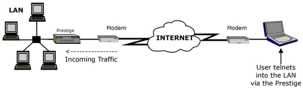
flowchart
graph LR
    A["LAN"] --> B["Prestige"]
    B --> C["Modem"]
    C --> D["INTERNET"]
    D --> E["Modem"]
    E --> F["User telnets into the LAN via the Prestige"]
    style A fill:#f9f,stroke:#333
    style B fill:#ccf,stroke:#333
    style C fill:#cfc,stroke:#333
    style D fill:#fcc,stroke:#333
    style E fill:#cff,stroke:#333
    style F fill:#ffc,stroke:#333
    note1["Incoming Traffic"] -.-> A
Figure 10-1 Telnet Configuration on a TCP/IP Network
10.3 FTP
You can upload and download Prestige firmware and configuration files using FTP. To use this feature, your computer must have an FTP client.
10.4 Web
You can use the Prestige's embedded web configurator for configuration and file management. See the online help for details.
10.5 Configuring Remote Management
Click Remote Management to open the following screen.
Remote Management Control
| Server Type | Access Status | Port | Secured Client IP |
| Telnet | All | 23 | 0.0.0.0 |
| FTP | All | 21 | 0.0.0.0 |
| Web | All | 80 | 0.0.0.0 |

Figure 10-2 Remote Management
The following table describes the labels in this screen.
Table 10-1 Remote Management
| LABEL | DESCRIPTION |
| Server Type | Each of these labels denotes a service that you may use to remotely manage the Prestige. |
| Access Status | Select the access interface. Choices are All, LAN Only, WAN Only and Disable. |
| Port | This field shows the port number for the remote management service. You may change the port number for a service in this field, but you must use the same port number to use that service for remote management. |
| Secured Client IP | The default 0.0.0.0 allows any client to use this service to remotely manage the Prestige. Type an IP address to restrict access to a client with a matching IP address. |
| Apply | Click Apply to save your settings back to the Prestige. |
| Cancel | Click Cancel to begin configuring this screen afresh. |
Chapter 11
Universal Plug-and-Play (UPnP)
This chapter introduces the UPnP feature in the web configurator.
11.1 Universal Plug and Play Overview
Universal Plug and Play (UPnP) is a distributed, open networking standard that uses TCP/IP for simple peer-to-peer network connectivity between devices. A UPnP device can dynamically join a network, obtain an IP address, convey its capabilities and learn about other devices on the network. In turn, a device can leave a network smoothly and automatically when it is no longer in use.
11.1.1 How do I know if I'm using UPnP?
UPnP hardware is identified as an icon in the Network Connections folder (Windows XP). Each UPnP compatible device installed on your network will appear as a separate icon. Selecting the icon of a UPnP device will allow you to access the information and properties of that device.
11.1.2 NAT Traversal
UPnP NAT traversal automates the process of allowing an application to operate through NAT. UPnP network devices can automatically configure network addressing, announce their presence in the network to other UPnP devices and enable exchange of simple product and service descriptions. NAT traversal allows the following:
▶ Dynamic port mapping
▶ Learning public IP addresses
➢ Assigning lease times to mappings
Windows Messenger is an example of an application that supports NAT traversal and UPnP.
See the Network Address Translation (NAT) chapter for further information about NAT.
11.1.3 Cautions with UPnP
The automated nature of NAT traversal applications in establishing their own services may present network security issues. Network information and configuration may also be obtained and modified by users in some network environments.
All UPnP-enabled devices may communicate freely with each other without additional configuration. Disable UPnP if this is not your intention.
11.2 UPnP and ZyXEL
ZyXEL has achieved UPnP certification from the Universal Plug and Play Forum Creates UPnP ^™ Implementers Corp. (UIC). ZyXEL's UPnP implementation supports IGD 1.0 (Internet Gateway Device). At the time of writing ZyXEL's UPnP implementation supports Windows Messenger 4.6 and 4.7 while Windows Messenger 5.0 and Xbox are still being tested.
UPnP broadcasts are only allowed on the LAN.
See later sections for examples of installing UPnP in Windows XP and Windows Me as well as an example of using UPnP in Windows.
11.2.1 Configuring UPnP
From the Site Map in the main menu, click UPnP under Advanced Setup to display the screen shown next.
UPNP
□ Enable the Universal Plug and Play(UPnP) Service
□ Allow users to make configuration changes through UPnP
Apply
Cancel
Figure 11-1 Configuring UPnP
The following table describes the labels in this screen.
Table 11-1 Configuring UPnP
| LABEL | DESCRIPTION |
| Enable the Universal Plug and Play (UPnP) Service | Select this checkbox to activate UPnP. Be aware that anyone could use a UPnP application to open the web configurator's login screen without entering the Prestige's IP address (although you must still enter the password to access the web configurator). |
| Allow users to make configuration changes through UPnP | Select this check box to allow UPnP-enabled applications to automatically configure the Prestige so that they can communicate through the Prestige, for example by using NAT traversal, UPnP applications automatically reserve a NAT forwarding port in order to communicate with another UPnP enabled device; this eliminates the need to manually configure port forwarding for the UPnP enabled application. |
| Apply | Click Apply to save the setting to the Prestige. |
| Cancel | Click Cancel to return to the previously saved settings. |
11.3 Installing UPnP in Windows Example
This section shows how to install UPnP in Windows Me and Windows XP.
11.3.1 Installing UPnP in Windows Me
Follow the steps below to install the UPnP in Windows Me.
Step 1. Click Start and Control Panel. Double-click Add/Remove Programs.
Step 2. Click on the Windows Setup tab and select Communication in the Components selection box. Click Details.
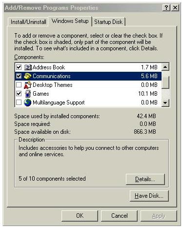
text_image
Add/Remove Programs Properties Install/Uninstall Windows Setup Startup Disk To add or remove a component, select or clear the check box. If the check box is shaded, only part of the component will be installed. To see what's included in a component, click Details. Components: Address Book 1.7 MB Communications 5.6 MB Desktop Themes 0.0 MB Games 10.1 MB Multilanguage Support 0.0 MB Space used by installed components: 42.4 MB Space required: 0.0 MB Space available on disk: 866.3 MB Description Includes accessories to help you connect to other computers and online services. 5 of 10 components selected Details... Have Disk... OK Cancel ApplyStep 3. In the Communications window, select the Universal Plug and Play check box in the Components selection box.
Step 4. Click OK to go back to the Add/Remove Programs Properties window and click Next.
Step 5. Restart the computer when prompted.
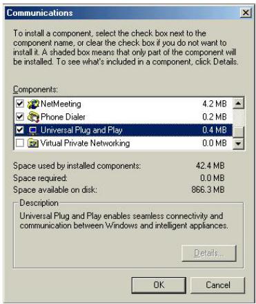
text_image
Communications To install a component, select the check box next to the component name, or clear the check box if you do not want to install it. A shaded box means that only part of the component will be installed. To see what's included in a component, click Details. Components: ✓ NetMeeting 4.2 MB ✓ Phone Dialer 0.2 MB ✓ Universal Plug and Play 0.4 MB ☐ Virtual Private Networking 0.0 MB Space used by installed components: 42.4 MB Space required: 0.0 MB Space available on disk: 866.3 MB Description Universal Plug and Play enables seamless connectivity and communication between Windows and intelligent appliances. Details... OK Cancel11.3.2 Installing UPnP in Windows XP
Follow the steps below to install the UPnP in Windows XP.
Step 1. Click Start and Control Panel.
Step 2. Double-click Network Connections.
Step 3. In the Network Connections window, click Advanced in the main menu and select Optional Networking Components ....
The Windows Optional Networking Components Wizard window displays.
Step 4. Select Networking Service in the Components selection box and click Details.
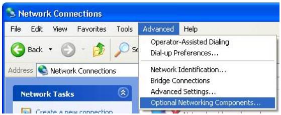
text_image
Network Connections File Edit View Favorites Tools Back Address Network Connections Network Tasks Create a new connection Advanced Help Operator-Assisted Dialing Dial-up Preferences... Network Identification... Bridge Connections Advanced Settings... Optional Networking Components...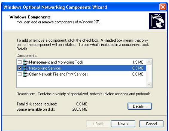
text_image
Windows Optional Networking Components Wizard Windows Components You can add or remove components of Windows XP. To add or remove a component, click the checkbox. A shaded box means that only part of the component will be installed. To see what's included in a component, click Details. Components: □ Management and Monitoring Tools 1.9 MB ✓ Networking Services 0.3 MB □ Other Network File and Print Services 0.0 MB Description: Contains a variety of specialized, network-related services and protocols. Total disk space required: 0.0 MB Space available on disk: 260.9 MB Details... < Back Next > CancelStep 5. In the Networking Services window, select the Universal Plug and Play check box.
Step 6. Click OK to go back to the Windows Optional Networking Component Wizard window and click Next.

text_image
Networking Services To add or remove a component, click the check box. A shaded box means that only part of the component will be installed. To see what's included in a component, click Details. Subcomponents of Networking Services: RIP Listener 0.0 MB Simple TCP/IP Services 0.0 MB Universal Plug and Play 0.2 MB Description: Allows your computer to discover and control Universal Plug and Play devices. Total disk space required: 0.0 MB Space available on disk: 260.8 MB Details... OK Cancel11.4 Using UPnP in Windows XP Example
This section shows you how to use the UPnP feature in Windows XP. You must already have UPnP installed in Windows XP and UPnP activated on the Prestige.
Make sure the computer is connected to a LAN port of the Prestige. Turn on your computer and the Prestige.
11.4.1 Auto-discover Your UPnP-enabled Network Device
Step 1. Click start and Control Panel. Double-click Network Connections. An icon displays under Internet Gateway.
Step 2. Right-click the icon and select Properties.
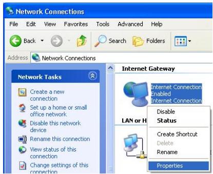
text_image
Network Connections File Edit View Favorites Tools Advanced Help Back Search Folders Address Network Connections Network Tasks Create a new connection Set up a home or small office network Disable this network device Rename this connection View status of this connection Change settings of this connection Internet Gateway Internet Connection Enabled Internet Connection Disable Status Create Shortcut Delete Rename PropertiesStep 3. In the Internet Connection Properties window, click Settings to see the port mappings there were automatically created.
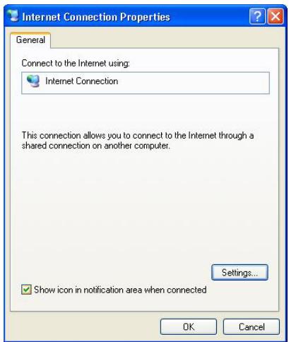
text_image
Internet Connection Properties General Connect to the Internet using: Internet Connection This connection allows you to connect to the Internet through a shared connection on another computer. Settings... Show icon in notification area when connected OK CancelStep 4. You may edit or delete the port mappings or click Add to manually add port mappings.
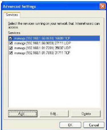
text_image
Advanced Settings Services Select the services running on your network that Internet users can access. Services ✓ msnws (192.168.1.66.9618) 16003 TCP ✓ msnws (192.168.1.66.9659) 27111 UDP ✓ msnws (192.168.1.91.7281) 25007 UDP ✓ msnws (192.168.1.91.7910) 31711 TCP Add Edit... Delete OK Cancel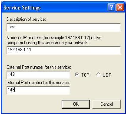
text_image
Service Settings Description of service: Test Name or IP address (for example 192.168.0.12) of the computer hosting this service on your network: 192.168.1.11 External Port number for this service: 143 Internal Port number for this service: 143 TCP UDP OK CancelWhen the UPnP-enabled device is disconnected from your computer, all port mappings will be deleted automatically.
Step 5. Select Show icon in notification area when connected option and click OK. An icon displays in the system tray

text_image
Internet Connection is now connected Click here for more information... upnp2 - Paint 6:43 PMStep 6. Double-click on the icon to display your current Internet connection status.
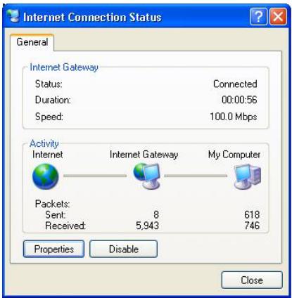
text_image
Internet Connection Status General Internet Gateway Status: Connected Duration: 00:00:56 Speed: 100.0 Mbps Activity Internet Internet Gateway My Computer Packets: Sent: 8 618 Received: 5,943 746 Properties Disable Close11.4.2 Web Configurator Easy Access
With UPnP, you can access the web-based configurator on the Prestige without finding out the IP address of the Prestige first. This comes helpful if you do not know the IP address of the Prestige.
Follow the steps below to access the web configurator.
Step 1. Click Start and then Control Panel.
Step 2. Double-click Network Connections.
Step 3. Select My Network Places under Other Places.
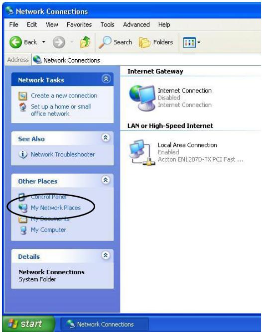
text_image
Network Connections File Edit View Favorites Tools Advanced Help Back Search Folders Address Network Connections Network Tasks Create a new connection Set up a home or small office network See Also Network Troubleshooter Other Places Control Panel My Network Places My Documents My Computer Details Network Connections System Folder Internet Gateway Internet Connection Disabled Internet Connection LAN or High-Speed Internet Local Area Connection Enabled Accton EN1207D-TX PCI Fast ... start Network ConnectionsStep 4. An icon with the description for each UPnP-enabled device displays under Local Network.
Step 5. Right-click on the icon for your Prestige and select Invoke. The web configurator login screen displays.
Step 6. Right-click on the icon for your Prestige and select Properties. A properties window displays with basic information about the Prestige.
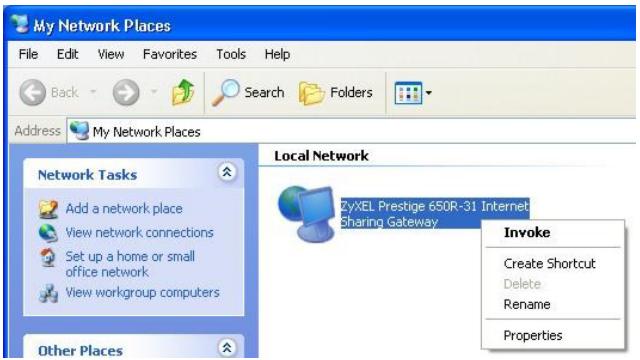
text_image
My Network Places File Edit View Favorites Tools Help Back Search Folders Address My Network Places Network Tasks Add a network place View network connections Set up a home or small office network View workgroup computers Other Places Local Network ZyXEL Prestige 650R-31 Internet Sharing Gateway Invoke Create Shortcut Delete Rename Properties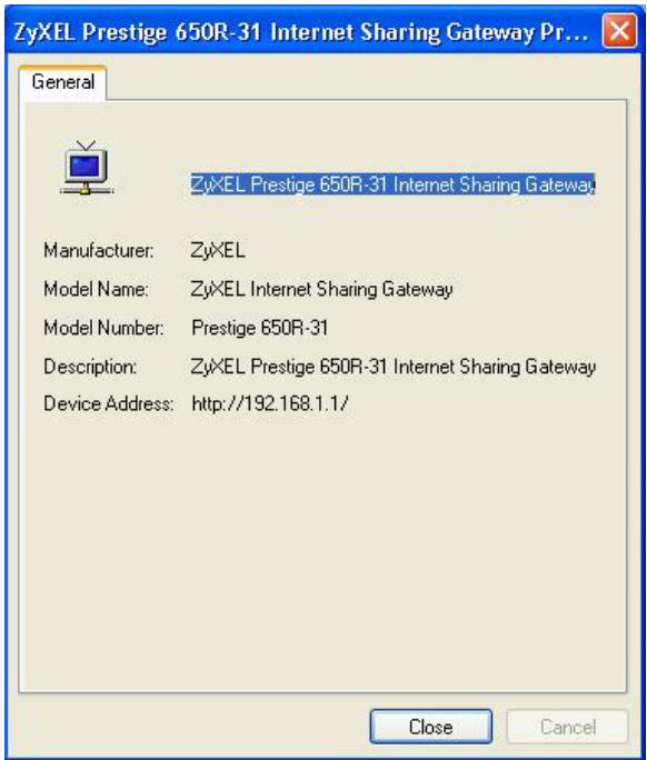
text_image
ZyXEL Prestige 650R-31 Internet Sharing Gateway Pr... General ZyXEL Prestige 650R-31 Internet Sharing Gateway Manufacturer: ZyXEL Model Name: ZyXEL Internet Sharing Gateway Model Number: Prestige 650R-31 Description: ZyXEL Prestige 650R-31 Internet Sharing Gateway Device Address: http://192.168.1.1/ Close CancelPart V:
Bandwidth Management
This part provides information on the functions and configuration of Bandwidth Management.
Chapter 12
Bandwidth Management
This chapter describes the functions and configuration of bandwidth management. Bandwidth management is not available on all models.
12.1 Bandwidth Management Overview
Bandwidth management allows you to allocate an interface's outgoing capacity to specific types of traffic. It can also help you make sure that the Prestige forwards certain types of traffic (especially real-time applications) with minimum delay. With the use of real-time applications such as Voice-over-IP (VoIP) increasing, the requirement for bandwidth allocation is also increasing.
Bandwidth management addresses questions such as:
• Who gets how much access to specific applications?
• What priority level should you give to each type of traffic?
• Which traffic must have guaranteed delivery?
• How much bandwidth should be allotted to guarantee delivery?
Bandwidth management also allows you to configure the allowed output for an interface to match what the network can handle. This helps reduce delays and dropped packets at the next routing device. For example, you can set the WAN interface speed to 1000kbps if the broadband device connected to the WAN port has an upstream speed of 1000kbps. All configuration screens display measurements in kbps (kilobits per second), but this User's Guide also uses Mbps (megabits per second) for brevity's sake.
12.2 Bandwidth Classes and Filters
Use bandwidth classes and child-classes to allocate specific amounts of bandwidth capacity (bandwidth budgets). Configure a bandwidth filter to define a bandwidth class (or child-class) based on a specific application and/or subnet. Use the Class Configuration tab (see section 12.9.1) to set up a bandwidth class's name, bandwidth allotment, and bandwidth filter. You can configure up to one bandwidth filter per bandwidth class. You can also configure bandwidth classes without bandwidth filters. However, it is recommended that you configure child-classes with filters for any classes that you configure without filters. The Prestige leaves the bandwidth budget allocated and unused for a class that does not have a filter itself or child-classes with filters. View your configured bandwidth classes and child-classes in the Class Setup tab (see section 12.9 for details).
The total of the configured bandwidth budgets for child-classes cannot exceed the configured bandwidth budget speed of the parent class.
12.3 Proportional Bandwidth Allocation
Bandwidth management allows you to define how much bandwidth each class gets; however, the actual bandwidth allotted to each class decreases or increases in proportion to actual available bandwidth.
12.4 Bandwidth Management Usage Examples
These examples show bandwidth management allotments on a WAN interface that is configured for 10Mbps.
12.4.1 Application-based Bandwidth Management Example
The bandwidth classes in the following example are based solely on application. Each bandwidth class (VoIP, Web, FTP, E-mail and Video) is allotted 2 Mbps.
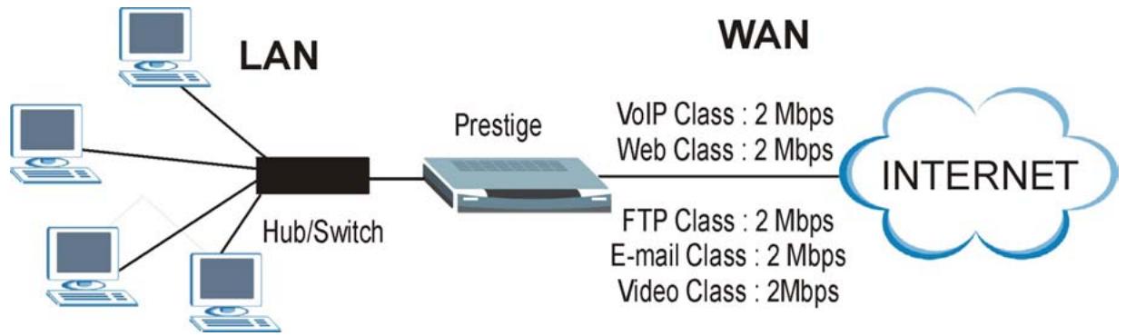
flowchart
graph LR
    A["Computer"] --> B["LAN"]
    C["Computer"] --> B
    D["Computer"] --> B
    E["Computer"] --> B
    F["Computer"] --> B
    G["Computer"] --> B
    H["Computer"] --> B
    I["Computer"] --> B
    J["Computer"] --> B
    K["Computer"] --> B
    L["Prestige"] --> M["Internet"]
    N["VoIP Class : 2 Mbps\nWeb Class : 2 Mbps\nFTP Class : 2 Mbps\nE-mail Class : 2 Mbps\nVideo Class : 2Mbps"] --> M
Figure 12-1 Application-based Bandwidth Management Example
12.4.2 Subnet-based Bandwidth Management Example
The following example uses bandwidth classes based solely on LAN subnets. Each bandwidth class (Subnet A and Subnet B) is allotted 5 Mbps.
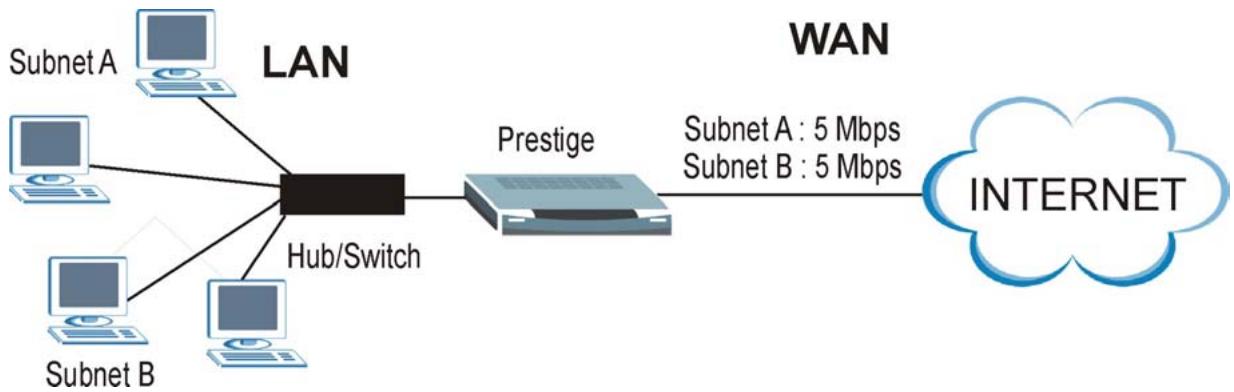
flowchart
graph LR
    A["Subnet A"] --> C["LAN"]
    B["Subnet B"] --> C
    D["Subnet A"] --> C
    E["Subnet B"] --> C
    C --> F["Prestige"]
    F --> G["Internet"]
    style G fill:#bbdefb,stroke:#333
    note right of F
        Subnet A : 5 Mbps
        Subnet B : 5 Mbps
    end
Figure 12-2 Subnet-based Bandwidth Management Example
12.4.3 Application and Subnet-based Bandwidth Management Example
The following example uses bandwidth classes based on LAN subnets and applications (specific applications in each subnet are allotted bandwidth).
Table 12-1 Application and Subnet-based Bandwidth Management Example
| TRAFFIC TYPE | FROM SUBNET A | FROM SUBNET B |
| VoIP | 1 Mbps | 1 Mbps |
| Web | 1 Mbps | 1 Mbps |
| FTP | 1 Mbps | 1 Mbps |
| 1 Mbps | 1 Mbps | |
| Video | 1 Mbps | 1 Mbps |
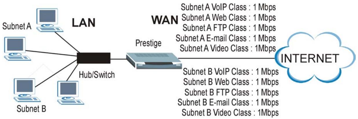
flowchart
graph LR
    A["LAN"] --> B["Hub/Switch"]
    B --> C["Prestige"]
    C --> D["INTERNET"]
    A --> E["Subnet A"]
    A --> F["Subnet B"]
    A --> G["Subnet A Web Class: 1 Mbps"]
    A --> H["Subnet A FTP Class: 1 Mbps"]
    A --> I["Subnet A E-mail Class: 1 Mbps"]
    A --> J["Subnet A Video Class: 1 Mbps"]
    C --> K["Subnet B VoIP Class: 1 Mbps"]
    C --> L["Subnet B Web Class: 1 Mbps"]
    C --> M["Subnet B FTP Class: 1 Mbps"]
    C --> N["Subnet B E-mail Class: 1 Mbps"]
    C --> O["Subnet B Video Class: 1 Mbps"]
Figure 12-3 Application and Subnet-based Bandwidth Management Example
12.5 Scheduler
The scheduler divides up an interface's bandwidth among the bandwidth classes. The Prestige has two types of scheduler: fairness-based and priority-based.
12.5.1 Priority-based Scheduler
With the priority-based scheduler, the Prestige forwards traffic from bandwidth classes according to the priorities that you assign to the bandwidth classes. The larger a bandwidth class's priority number is, the higher the priority. Assign real-time applications (like those using audio or video) a higher priority number to provide smoother operation.
12.5.2 Fairness-based Scheduler
The Prestige divides bandwidth equally among bandwidth classes when using the fairness-based scheduler; thus preventing one bandwidth class from using all of the interface's bandwidth.
12.6 Maximize Bandwidth Usage
The maximize bandwidth usage option (see Figure 12-7) allows the Prestige to divide up any available bandwidth on the interface (including unallocated bandwidth and any allocated bandwidth that a class is not using) among the bandwidth classes that require more bandwidth.
When you enable maximize bandwidth usage, the Prestige first makes sure that each bandwidth class gets up to its bandwidth allotment. Next, the Prestige divides up an interface's available bandwidth (bandwidth that is unbudgeted or unused by the classes) depending on how many bandwidth classes require more bandwidth
and on their priority levels. When only one class requires more bandwidth, the Prestige gives extra bandwidth to that class.
When multiple classes require more bandwidth, the Prestige gives the highest priority classes the available bandwidth first (as much as they require, if there is enough available bandwidth), and then to lower priority classes if there is still bandwidth available. The Prestige distributes the available bandwidth equally among classes with the same priority level.
12.6.1 Reserving Bandwidth for Non-Bandwidth Class Traffic
Do the following three steps to configure the Prestige to allow bandwidth for traffic that is not defined in a bandwidth filter.
Step 1. Leave some of the interface's bandwidth unbudgeted.
Step 2. Do not enable the interface's Maximize Bandwidth Usage option.
Step 3. Do not enable bandwidth borrowing on the child-classes that have the root class as their parent (see section 12.7).
12.6.2 Maximize Bandwidth Usage Example
Here is an example of a Prestige that has maximized bandwidth usage enabled on an interface. The first figure shows each bandwidth class's bandwidth budget and priority. The classes are set up based on subnets. The interface is set to 10 Mbps. Each subnet is allocated 2 Mbps. The unbudgeted 2 Mbps allows traffic not defined in one of the bandwidth filters to go out when you do not select the maximize bandwidth option.
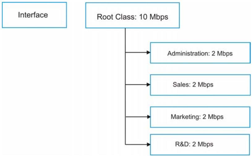
flowchart
graph TD
    A["Interface"] --> B["Root Class: 10 Mbps"]
    B --> C["Administration: 2 Mbps"]
    B --> D["Sales: 2 Mbps"]
    B --> E["Marketing: 2 Mbps"]
    B --> F["R&D: 2 Mbps"]
Figure 12-4 Bandwidth Allotment Example
The following figure shows the bandwidth usage with the maximize bandwidth usage option enabled. The Prestige divides up the unbudgeted 2 Mbps among the classes that require more bandwidth. If the administration department only uses 1 Mbps of the budgeted 2 Mbps, the Prestige also divides the remaining 1 Mbps among the classes that require more bandwidth. Therefore, the Prestige divides a total of 3 Mbps total of unbudgeted and unused bandwidth among the classes that require more bandwidth.
In this case, suppose that all of the classes except for the administration class need more bandwidth.
Each class gets up to its budgeted bandwidth. The administration class only uses 1 Mbps of its budgeted 2 Mbps.
Sales and Marketing are first to get extra bandwidth because they have the highest priority (6). If they each require 1.5 Mbps or more of extra bandwidth, the Prestige divides the total 3 Mbps total of unbudgeted and unused bandwidth equally between the sales and marketing departments (1.5 Mbps extra to each for a total of 3.5 Mbps for each) because they both have the highest priority level.
R&D requires more bandwidth but only gets its budgeted 2 Mbps because all of the unbudgeted and unused bandwidth goes to the higher priority sales and marketing classes.
The Prestige does not send any traffic that is not defined in the bandwidth filters because all of the unbudgeted bandwidth goes to the classes that need it.
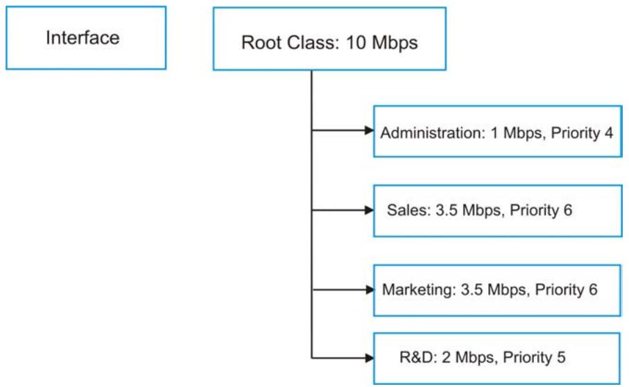
flowchart
graph TD
    A["Interface"] --> B["Root Class: 10 Mbps"]
    B --> C["Administration: 1 Mbps, Priority 4"]
    B --> D["Sales: 3.5 Mbps, Priority 6"]
    B --> E["Marketing: 3.5 Mbps, Priority 6"]
    B --> F["R&D: 2 Mbps, Priority 5"]
Figure 12-5 Maximize Bandwidth Usage Example
12.7 Bandwidth Borrowing
Bandwidth borrowing allows a child-class to borrow unused bandwidth from its parent class, whereas maximize bandwidth usage allows bandwidth classes to borrow any unused or unbudgeted bandwidth on the whole interface.
Enable bandwidth borrowing on a child-class to allow the child-class to use its parent class's unused bandwidth. A parent class's unused bandwidth is given to the highest priority child-class first. The child-class can also borrow bandwidth from a higher parent class (grandparent class) if the child-class's parent class is also configured to borrow bandwidth from its parent class. This can go on for as many levels as are configured to borrow bandwidth from their parent class (see section 12.7.1).
The total of the bandwidth allotments for child-classes cannot exceed the bandwidth allotment of their parent class. The Prestige uses the scheduler to divide a parent class's unused bandwidth among the child-classes.
12.7.1 Bandwidth Borrowing Example
Here is an example of bandwidth management with classes configured for bandwidth borrowing. The classes are set up based on departments and individuals within certain departments.
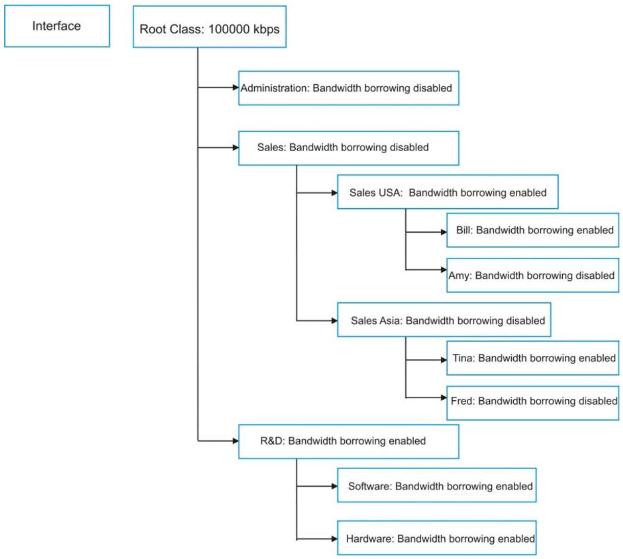
flowchart
graph TD
    A["Interface"] --> B["Root Class: 100000 kbps"]
    B --> C["Administration: Bandwidth borrowing disabled"]
    B --> D["Sales: Bandwidth borrowing disabled"]
    D --> E["Sales USA: Bandwidth borrowing enabled"]
    D --> F["Sales Asia: Bandwidth borrowing disabled"]
    F --> G["Bill: Bandwidth borrowing enabled"]
    F --> H["Amy: Bandwidth borrowing disabled"]
    F --> I["Tina: Bandwidth borrowing enabled"]
    F --> J["Fred: Bandwidth borrowing disabled"]
    B --> K["R&D: Bandwidth borrowing enabled"]
    K --> L["Software: Bandwidth borrowing enabled"]
    K --> M["Hardware: Bandwidth borrowing enabled"]
Figure 12-6 Bandwidth Borrowing Example
The Bill class can borrow unused bandwidth from the Sales USA class because the Bill class has bandwidth borrowing enabled.
The Bill class can also borrow unused bandwidth from the Sales class because the Sales USA class also has bandwidth borrowing enabled.
The Bill class cannot borrow unused bandwidth from the Root class because the Sales class has bandwidth borrowing disabled.
The Amy class cannot borrow unused bandwidth from the Sales USA class because the Amy class has bandwidth borrowing disabled.
The R&D Software and Hardware classes can both borrow unused bandwidth from the R&D class because the R&D Software and Hardware classes both have bandwidth borrowing enabled.
The R&D Software and Hardware classes can also borrow unused bandwidth from the Root class because the R&D class also has bandwidth borrowing enabled.
12.7.2 Maximize Bandwidth Usage With Bandwidth Borrowing
If you configure both maximize bandwidth usage (on the interface) and bandwidth borrowing (on individual child-classes), the Prestige functions as follows.
- The Prestige sends traffic according to each bandwidth class's bandwidth budget.
- The Prestige assigns a parent class's unused bandwidth to its child-classes that have more traffic than their budgets and have bandwidth borrowing enabled. The Prestige gives priority to bandwidth child-classes of higher priority and treats bandwidth classes of the same priority equally.
- The Prestige assigns any remaining unused or unbudgeted bandwidth on the interface to any bandwidth class that requires it. The Prestige gives priority to bandwidth classes of higher priority and treats bandwidth classes of the same level equally.
- The Prestige assigns any remaining unbudgeted bandwidth to traffic that does not match any of the bandwidth classes.
12.8 Configuring Summary
Click BW Manager, Summary to open the Summary screen.
Enable bandwidth management on an interface and set the maximum allowed bandwidth for that interface.
BW Manager · Summary
BW Manager manages the bandwidth of traffic flowing out of router on the specific interface. BW Manager can be switched on/off independently for each interface.
| Server Type | Active | Speed (kbps) | Scheduler | Max Bandwidth Usage |
| LAN | ☑ | 50000 | Fairness-Based | ☑ Yes |
| WLAN | ☐ | 0 | Priority-Based | ☐ Yes |
| WAN | ☐ | 0 | Priority-Based | ☐ Yes |

Figure 12-7 Bandwidth Manager: Summary
The following table describes the labels in this screen.
Table 12-2 Bandwidth Manager: Summary
| LABEL | DESCRIPTION |
| LANWLANWAN | These read-only labels represent the physical interfaces. |
| Active | Select an interface's check box to enable bandwidth management on that interface. Not all interfaces are available on every Prestige. |
| Speed (kbps) | Enter the amount of bandwidth for this interface that you want to allocate using bandwidth management.This appears as the bandwidth budget of the interface's root class (see section 12.9). The recommendation is to set this speed to match what the device connected to the port can handle. For example, set the WAN interface speed to 1000 kbps if the broadband device connected to the WAN port has an upstream speed of 1000 kbps. |
Table 12-2 Bandwidth Manager: Summary
| LABEL | DESCRIPTION |
| Scheduler | Select either Priority-Based or Fairness-Based from the drop-down menu to control the traffic flow.Select Priority-Based to give preference to bandwidth classes with higher priorities.Select Fairness-Based to treat all bandwidth classes equally. See section 12.5. |
| Maximize Bandwidth Usage | Select this check box to have the Prestige divide up all of the interface’s unallocated and/or unused bandwidth among the bandwidth classes that require bandwidth. Do not select this if you want to reserve bandwidth for traffic that does not match a bandwidth class (see section 12.6.1) or you want to limit the speed of this interface (see the Speed field description). |
| Back | Click Back to go to the main BW Manager screen. |
| Apply | Click Apply to save your settings back to the Prestige. |
| Cancel | Click Cancel to begin configuring this screen afresh. |
12.9 Configuring Class Setup
The class setup screen displays the configured bandwidth classes by individual interface. Select an interface and click the buttons to perform the actions described next. Click “+” to expand the class tree or click “-” to collapse the class tree. Each interface has a permanent root class. The bandwidth budget of the root class is equal to the speed you configured on the interface (see section 12.8 to configure the speed of the interface). Configure child-class layers for the root class.
To add or delete child classes on an interface, click BW Manager, then Class Setup. The screen appears as shown (with example classes).
The example reserves 15 Mbps of unbudgeted bandwidth for traffic that is not defined in the bandwidth filters (see section 12.6.1). The Administration, Sales USA and Sales Asia bandwidth classes each have bigger bandwidth budgets than the total of the budgets of their child-classes. The child-classes can borrow the extra bandwidth as long as they have bandwidth borrowing enabled (see section 12.7).
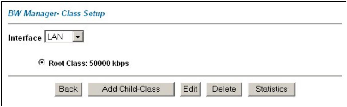
text_image
BW Manager- Class Setup Interface LAN ● Root Class: 50000 kbps Back Add Child-Class Edit Delete StatisticsFigure 12-8 Bandwidth Manager: Class Setup
The following table describes the labels in this screen.
Table 12-3 Bandwidth Manager: Class Setup
| LABEL | DESCRIPTION |
| Interface | Select an interface from the drop-down list box for which you wish to set up classes. |
| Back | Click Back to go to the main BW Manager screen. |
| Add Child-Class | Click Add Child-class to add a sub-class. |
| Edit | Click Edit to configure the selected class. You cannot edit the root class. |
| Delete | Click Delete to delete the class and all its child-classes. You cannot delete the root class. |
| Statistics | Click Statistics to display the status of the selected class. |
12.9.1 Bandwidth Manager Class Configuration
Configure a bandwidth management class in the Class Configuration screen. You must use the Bandwidth Manager - Summary screen to enable bandwidth management on an interface before you can configure classes for that interface.
To add a child class, click BW Manager, then Class Setup. Click the Add Child-Class button to open the following screen.
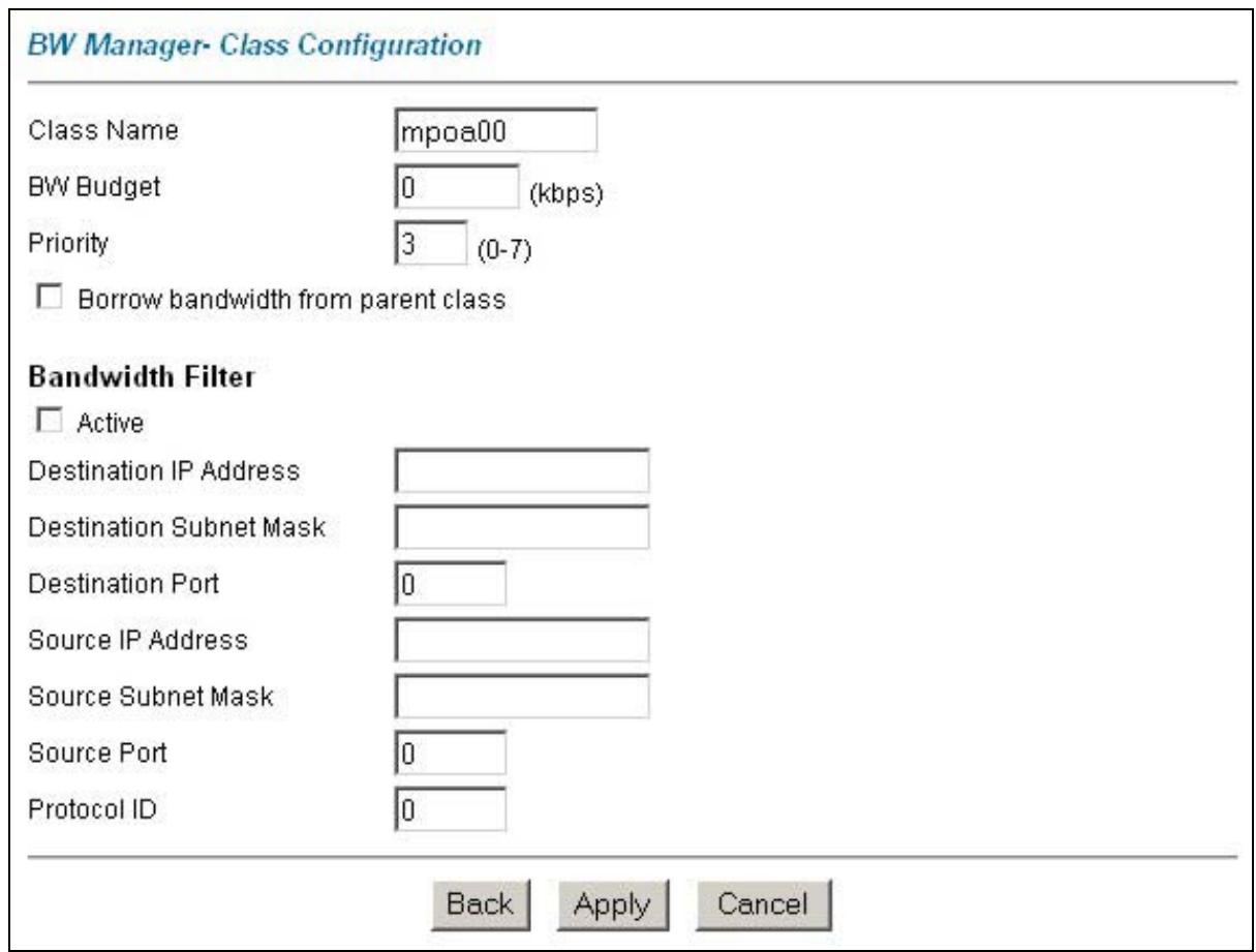
text_image
BW Manager- Class Configuration Class Name mpoa00 BW Budget 0 (kbps) Priority 3 (0-7) Borrow bandwidth from parent class Bandwidth Filter Active Destination IP Address Destination Subnet Mask Destination Port 0 Source IP Address Source Subnet Mask Source Port 0 Protocol ID 0 Back Apply CancelFigure 12-9 Bandwidth Manager: Class Configuration
The following table describes the labels in this screen.
Table 12-4 Bandwidth Manager: Class Configuration
| LABEL | DESCRIPTION |
| Class Name | Use the auto-generated name or enter a descriptive name of up to 20 alphanumeric characters, including spaces. |
| BW Budget (kbps) | Specify the maximum bandwidth allowed for the class in kbps. The recommendation is a setting between 20 kbps and 20000 kbps for an individual class. |
Table 12-4 Bandwidth Manager: Class Configuration
| LABEL | DESCRIPTION |
| Priority | Enter a number between 0 and 7 to set the priority of this class. The higher the number, the higher the priority. The default setting is 3. |
| Borrow bandwidth from parent class | Select this option to allow a child-class to borrow bandwidth from its parent class if the parent class is not using up its bandwidth budget.Bandwidth borrowing is governed by the priority of the child-classes. That is, a child-class with the highest priority (7) is the first to borrow bandwidth from its parent class.Do not select this for the classes directly below the root class if you want to leave bandwidth available for other traffic types (see 12.6.1) or you want to set the interface's speed to match what the next device in network can handle (see the Speed field description in Table 12-2). |
| Bandwidth Filter | |
| Active | Select the check box to have the Prestige use this bandwidth filter when it performs bandwidth management.You must enter a value in at least one of the following fields (other than the Destination Subnet Mask fields which are only available when you enter the destination or source IP address). |
| Destination IP Address | Enter the destination IP address in dotted decimal notation. |
| Destination Subnet Mask | Enter the destination subnet mask. This field is N/A if you do not specify a Destination IP Address. Refer to the appendix for more information on IP subnetting. |
| Destination Port | Enter the port number of the destination. |
| Source IP Address | Enter the source IP address. |
| Source Subnet Mask | Enter the source subnet mask. This field is N/A if you do not specify a Source IP Address. Refer to the appendix for more information on IP subnetting. |
| Source Port | Enter the port number of the source. See the following table for some common services and port numbers. |
| Protocol ID | Enter the protocol ID (service type) number, for example: 1 for ICMP, 6 for TCP or 17 for UDP. |
| Back | Click Back to go to the main BW Manager screen. |
| Apply | Click Apply to save your changes back to the Prestige. |
Table 12-4 Bandwidth Manager: Class Configuration
| LABEL | DESCRIPTION |
| Cancel | Click Cancel to begin configuring this screen afresh. |
Table 12-5Services and Port Numbers
| SERVICES | PORT NUMBER |
| ECHO | 7 |
| FTP (File Transfer Protocol) | 21 |
| SMTP (Simple Mail Transfer Protocol) | 25 |
| DNS (Domain Name System) | 53 |
| Finger | 79 |
| HTTP (Hyper Text Transfer protocol or WWW, Web) | 80 |
| POP3 (Post Office Protocol) | 110 |
| NNTP (Network News Transport Protocol) | 119 |
| SNMP (Simple Network Management Protocol) | 161 |
| SNMP trap | 162 |
| PPTP (Point-to-Point Tunneling Protocol) | 1723 |
12.9.2 Bandwidth Management Statistics
Use the Bandwidth Management Statistics screen to view network performance information. Click the Statistics button in the Class Setup screen to open the Statistics screen.
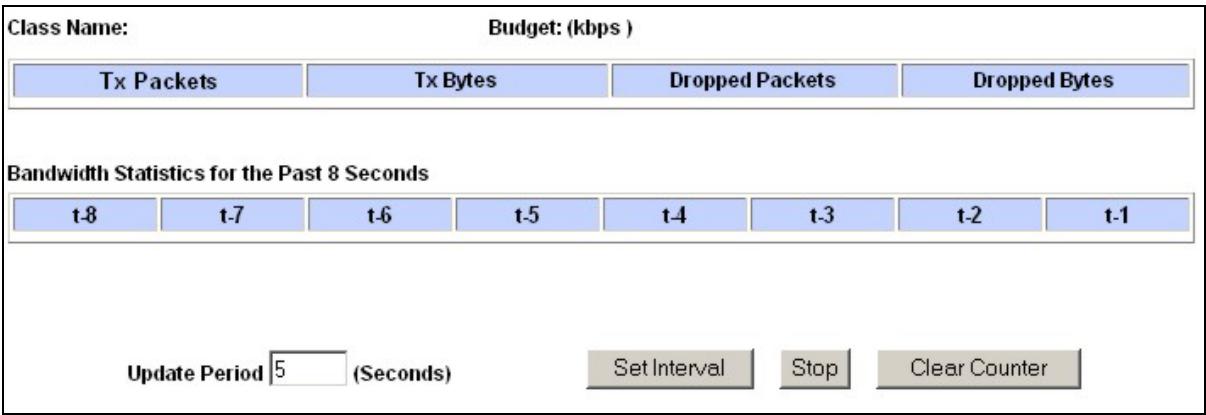
text_image
Class Name: Budget: (kbps ) Tx Packets Tx Bytes Dropped Packets Dropped Bytes Bandwidth Statistics for the Past 8 Seconds t-8 t-7 t-6 t-5 t-4 t-3 t-2 t-1 Update Period 5 (Seconds) Set Interval Stop Clear CounterFigure 12-10 Bandwidth Management Statistics
The following table describes the labels in this screen.
Table 12-6 Bandwidth Management Statistics
| LABEL | DESCRIPTION |
| Class Name | This field displays the name of the class the statistics page is showing. |
| Budget (kbps) | This field displays the amount of bandwidth allocated to the class. |
| Tx Packets | This field displays the total number of packets transmitted. |
| TX Bytes | This field displays the total number of bytes transmitted. |
| Dropped Packets | This field displays the total number of packets dropped. |
| Dropped Bytes | This field displays the total number of bytes dropped. |
| Bandwidth Statistics for the Past 8 Seconds (t-8 to t-1) | |
| This field displays the bandwidth statistics (in bps) for the past one to eight seconds. For example, t-1 means one second ago. | |
| Update Period (seconds) | Enter the time interval in seconds to define how often the information should be refreshed. |
| Set Interval | Click Set Interval to apply the new update period you entered in the Update Period field above. |
| Stop Update | Click Stop Update to stop the browser from refreshing bandwidth management statistics. |
| Clear Counter | Click Clear Counter to clear all of the bandwidth management statistics. |
12.10 Configuring Monitor
To view the Prestige's bandwidth usage and allotments, click BW Manager, then Monitor. The screen appears as shown.
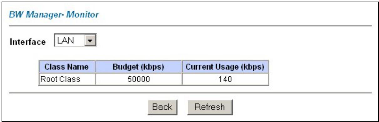
text_image
BW Manager- Monitor Interface LAN Class Name Budget (kbps) Current Usage (kbps) Root Class 50000 140 Back RefreshFigure 12-11 Bandwidth Manager Monitor
The following table describes the labels in this screen.
Table 12-7 Bandwidth Manager Monitor
| LABEL | DESCRIPTION |
| Interface | Select an interface from the drop-down list box to view the bandwidth usage of its bandwidth classes. |
| Class Name | This field displays the name of the class. |
| Budget (kbps) | This field displays the amount of bandwidth allocated to the class. |
| Current Usage (kbps) | This field displays the amount of bandwidth that each class is using. |
| Back | Click Back to go to the main BW Manager screen. |
| Refresh | Click Refresh to update the page. |
Part VI:
Maintenance
This part covers the maintenance screens.
Chapter 13
Maintenance
This chapter displays system information such as ZyNOS firmware, port IP addresses and port traffic statistics.
13.1 Maintenance Overview
Use the maintenance screens to view system information, upload new firmware, manage configuration and restart your Prestige.
13.2 System Status Screen
Click System Status to open the following screen, where you can use to monitor your Prestige. Note that these fields are READ-ONLY and are meant to be used for diagnostic purposes.
System Status
System Status
System Name :
ZyNOS FMV Version: V3.40(IS.2) | 6/16/2003
DSL FW Version: Alcatel, Version 3.9.122
Standard: Multi-Mode
WAN Information
IP Address: 0.0.0.0
IP Subnet Mask: 0.0.0.0
Default Gateway: 0.0.0.0
VPI/VCI: 8/35
LAN Information
MAC Address: 00:a0:c5:74:55:8a
IP Address: 192.168.1.1
IP Subnet Mask: 255.255.255.0
DHCP: Server
DHCP Start IP: 192.168.1.33
DHCP Pool Size: 32
Show Statistics
Figure 13-1 System Status
The following table describes the labels in this screen.
Table 13-1 System Status
| LABEL | DESCRIPTION |
| System Status | |
| System Name | This is the name of your Prestige. It is for identification purposes. |
| ZyNOS F/W Version | This is the ZyNOS firmware version and the date created. ZyNOS is ZyXEL's proprietary Network Operating System design. |
| DSL FW Version | This is the DSL firmware version associated with your Prestige. |
| Standard | This is the standard that your Prestige is using. |
| WAN Information | |
| IP Address | This is the WAN port IP address. |
| IP Subnet Mask | This is the WAN port IP subnet mask. |
| Default Gateway | This is the IP address of the default gateway, if applicable. |
| VPI/VCI | This is the Virtual Path Identifier and Virtual Channel Identifier that you entered in the first Wizard screen. |
| LAN Information | |
| MAC Address | This is the MAC (Media Access Control) or Ethernet address unique to your Prestige. |
| IP Address | This is the LAN port IP address. |
| IP Subnet Mask | This is the LAN port IP subnet mask. |
| DHCP | This is the WAN port DHCP role - Server, Relay (not all Prestige models) or None. |
| DHCP Start IP | This is the first of the contiguous addresses in the IP address pool. |
| DHCP Pool Size | This is the number of IP addresses in the IP address pool. |
Table 13-1 System Status
| LABEL | DESCRIPTION |
| Show Statistics | Click Show Statistics to see router performance statistics such as number of packets sent and number of packets received for each port. |
13.2.1 System Statistics
Click Show Statistics in the System Status screen to open the following screen. Read-only information here includes port status and packet specific statistics. Also provided are "system up time" and "poll interval(s)". The Poll Interval(s) field is configurable.
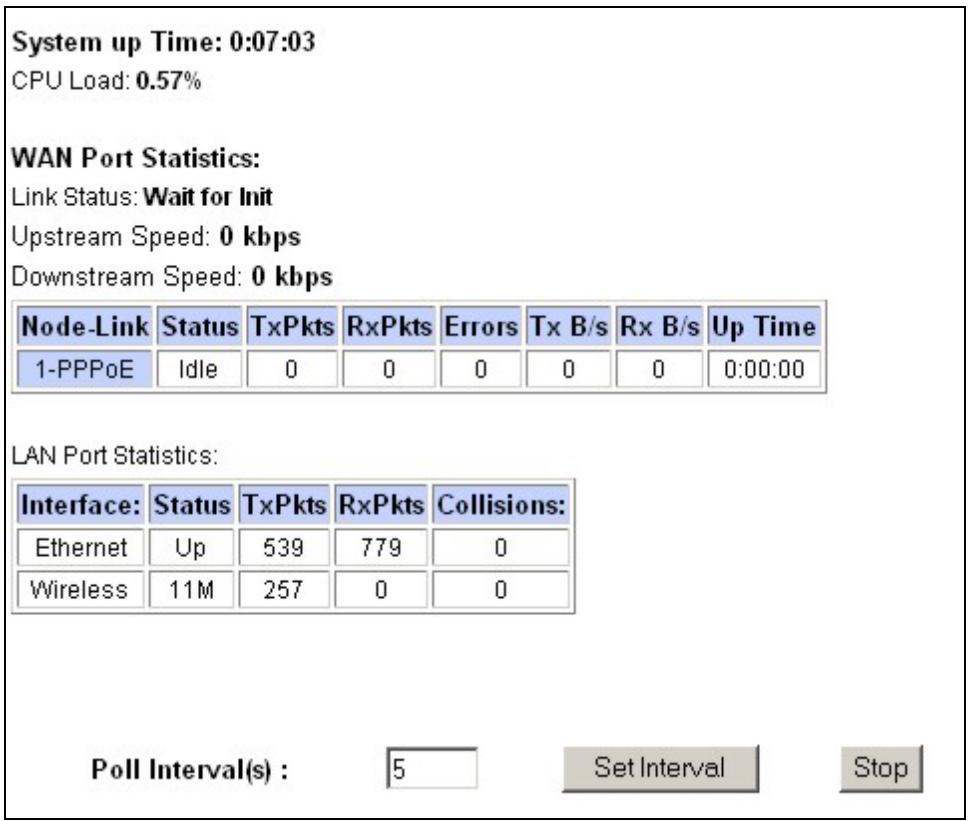
text_image
System up Time: 0:07:03 CPU Load: 0.57% WAN Port Statistics: Link Status: Wait for Init Upstream Speed: 0 kbps Downstream Speed: 0 kbps Node-Link Status TxPkts RxPkts Errors Tx B/s Rx B/s Up Time 1-PPPoE Idle 0 0 0 0 0:00:00 LAN Port Statistics: Interface: Status TxPkts RxPkts Collisions: Ethernet Up 539 779 0 Wireless 11M 257 0 0 Poll Interval(s) : 5 Set Interval StopFigure 13-2 System Status: Show Statistics
The following table describes the labels in this screen.
Table 13-2 System Status: Show Statistics
| LABEL | DESCRIPTION |
| System up Time | This is the elapsed time the system has been up. |
| CPU Load | This field specifies the percentage of CPU utilization. |
| WAN Port Statistics | This is the WAN port. |
| Link Status | This is the status of your WAN link. |
| Transfer Rate | This is the transfer rate in kbps. |
| Upstream Speed | This is the upstream speed of your Prestige. |
| Downstream Speed | This is the downstream speed of your Prestige. |
| Node-Link | This field displays the remote node index number and link type. Link types are PPPoA, ENET, RFC 1483 and PPPoE . |
| LAN Port Statistics | This is the LAN port. |
| Interface | This field displays the type of port. |
| Status | For the WAN port, this displays the port speed and duplex setting if you're using Ethernet encapsulation and down (line is down), idle (line (ppp) idle), dial (starting to trigger a call) and drop (dropping a call) if you're using PPPoE encapsulation.For a LAN port, this shows the port speed and duplex setting. |
| TxPkts | This field displays the number of packets transmitted on this port. |
| RxPkts | This field displays the number of packets received on this port. |
| Errors | This field displays the number of error packets on this port. |
| Tx B/s | This field displays the number of bytes transmitted in the last second. |
| Rx B/s | This field displays the number of bytes received in the last second. |
| Up Time | This field displays the elapsed time this port has been up. |
Table 13-2 System Status: Show Statistics
| LABEL | DESCRIPTION |
| Collisions | This is the number of collisions on this port. |
| Poll Interval(s) | Type the time interval for the browser to refresh system statistics. |
| Set Interval | Click this button to apply the new poll interval you entered in the Poll Interval field above. |
| Stop | Click this button to halt the refreshing of the system statistics. |
13.3 DHCP Table Screen
DHCP (Dynamic Host Configuration Protocol, RFC 2131 and RFC 2132) allows individual clients to obtain TCP/IP configuration at start-up from a server. You can configure the Prestige as a DHCP server or disable it. When configured as a server, the Prestige provides the TCP/IP configuration for the clients. If set to None, DHCP service will be disabled and you must have another DHCP server on your LAN, or else the computer must be manually configured.
Click MAINTENANCE, and then the DHCP Table tab. Read-only information here relates to your DHCP status. The DHCP table shows current DHCP client information (including IP Address, Host Name and MAC Address) of all network clients using the DHCP server.
DHCP Table
| Host Name | IP Address | MAC Address |
| TWer-4 | 192.168.1.33 | 00-00-E8-7C-14-80 |
| 192.168.1.34 | 00-02-DD-32-91-6A | |
| oemcomputer | 192.168.1.35 | 00-A0-C5-41-A7-96 |
Figure 13-3 DHCP Table
The following table describes the labels in this screen.
Table 13-3 DHCP Table
| LABEL | DESCRIPTION |
| Host Name | This is the name of the host computer. |
| IP Address | This field displays the IP address relative to the Host Name field. |
| MAC Address | This field displays the MAC (Media Access Control) address of the computer with the displayed host name.Every Ethernet device has a unique MAC address. The MAC address is assigned at the factory and consists of six pairs of hexadecimal characters, for example, 00:A0:C5:00:00:02. |
13.4 Wireless Screens
These read-only screens display information about the Prestige's wireless LAN.
13.4.1 Association List
This screen displays the MAC address(es) of the wireless clients that are currently logged in to the network. Click Wireless LAN and then Association List to open the screen shown next.
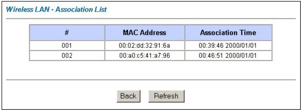
text_image
Wireless LAN - Association List # MAC Address Association Time 001 00:02:dd:32:91:6a 00:39:46 2000/01/01 002 00:a0:c5:41:a7:96 00:46:51 2000/01/01 Back RefreshFigure 13-4 Association List
The following table describes the labels in this screen.
Table 13-4 Association List
| LABEL | DESCRIPTION |
| # | This is the index number of an associated wireless client. |
| MAC Address | This field displays the MAC (Media Access Control) address of an associated wireless station. Every Ethernet device has a unique MAC address. The MAC address is assigned at the factory and consists of six pairs of hexadecimal characters, for example, 00:A0:C5:00:00:02. |
| Association Time | This field displays how long a wireless station has been associated to the Prestige. |
| Back | Click Back to go to the main Wireless LAN screen. |
| Refresh | Click Refresh to renew the information in the table. |
13.4.2 Channel Usage Table
This screen displays the state of the channels within the Prestige's transmission range. Click Wireless LAN and then Channel Usage Table to open the screen shown next.
Wireless LAN · Channel Usage Table
| Channel | Activity |
| 1 | Yes |
| 2 | Yes |
| 3 | Yes |
| 4 | Yes |
| 5 | Yes |
| 6 | Yes |
| 7 | Yes |
| 8 | No |
| 9 | No |
| 10 | No |
| 11 | Yes |

Figure 13-5 Channel Usage Table
The following table describes the labels in this screen.
Table 13-5 Channel Usage Table
| LABEL | DESCRIPTION |
| Channel | This is the index number of the channel. |
| IP Address | This field displays Yes if another AP or Ad-hoc network is using the channel within the Prestige's transmission range. |
| Back | Click Back to go to the main Wireless LAN screen. |
| Refresh | Click Refresh to renew the information in the table. |
13.5 Diagnostic Screens
These read-only screens display information to help you identify problems with the Prestige. Click Diagnostic to display the following screen.
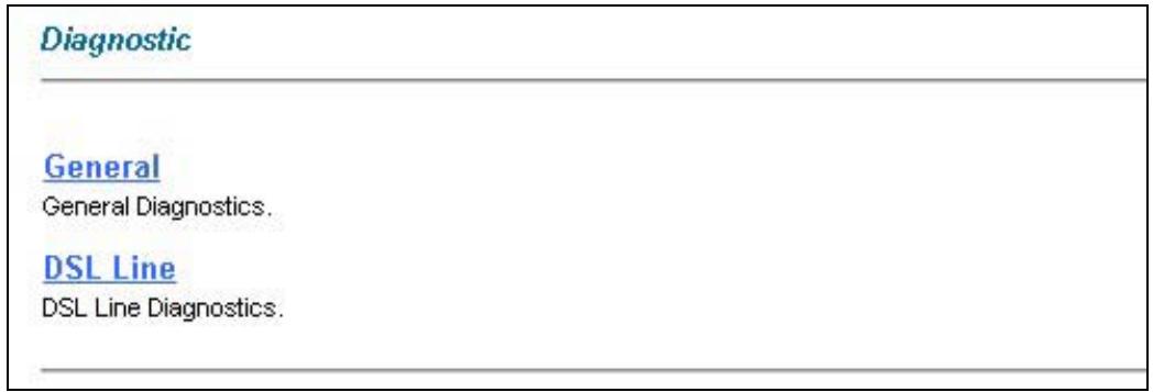
text_image
Diagnostic General General Diagnostics. DSL Line DSL Line Diagnostics.Figure 13-6 Diagnostic
13.5.1 Diagnostic General Screen
Click Diagnostic and then General to open the screen shown next.
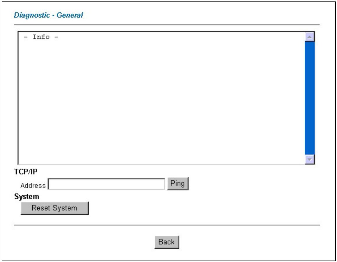
text_image
Diagnostic - General - Info - TCP/IP Address Ping System Reset System BackFigure 13-7 Diagnostic General
The following table describes the labels in this screen.
Table 13-6 Diagnostic General
| LABEL | DESCRIPTION |
| TCP/IP Address | Type the IP address of a computer that you want to ping in order to test a connection. |
| Ping | Click this button to ping the IP address that you entered. |
Table 13-6 Diagnostic General
| LABEL | DESCRIPTION |
| Reset System | Click this button to reboot the Prestige. A warning dialog box is then displayed asking you if you're sure you want to reboot the system. Click OK to proceed. |
| Back | Click this button to go back to the main Diagnostic screen. |
13.5.2 Diagnostic DSL Line Screen
Click Diagnostic and then DSL Line to open the screen shown next.
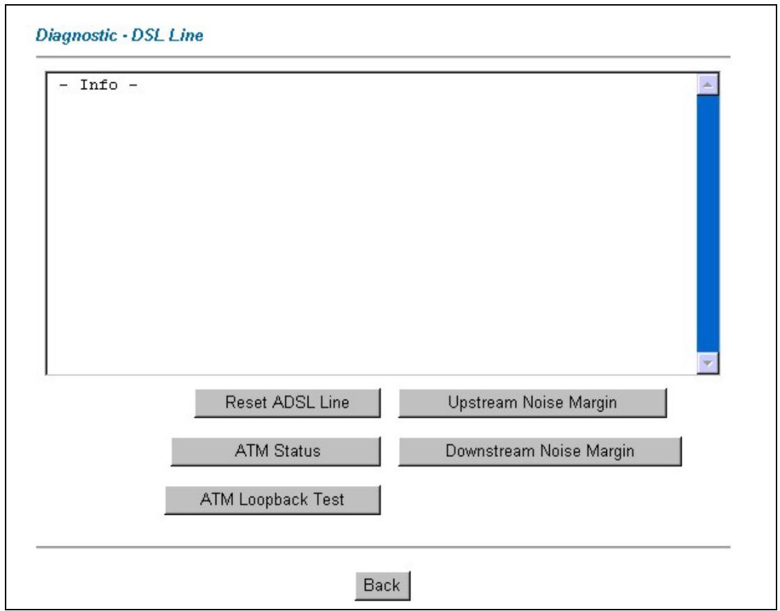
text_image
Diagnostic - DSL Line - Info - Reset ADSL Line Upstream Noise Margin ATM Status Downstream Noise Margin ATM Loopback Test BackFigure 13-8 Diagnostic DSL Line
The following table describes the labels in this screen.
Table 13-7 Diagnostic DSL Line
| LABEL | DESCRIPTION |
| Reset ADSL Line | Click this button to reinitialize the ADSL line. The large text box above then displays the progress and results of this operation, for example:"Start to reset ADSLLoading ADSL modem F/W...Reset ADSL Line Successfully!" |
| ATM Status | Click this button to view ATM status. |
| ATM Loopback Test | Click this button to start the ATM loopback test. Make sure you have configured at least one PVC with proper VPIs/VCIs before you begin this test. The Prestige sends an OAM F5 packet to the DSLAM/ATM switch and then returns it (loops it back) to the Prestige. The ATM loopback test is useful for troubleshooting problems with the DSLAM and ATM network. |
| Upstream Noise Margin | Click this button to display the upstream noise margin. |
| Downstream Noise Margin | Click this button to display the downstream noise margin. |
| Back | Click this button to go back to the main Diagnostic screen. |
13.6 Firmware Screen
Find firmware at www.zyxel.com in a file that (usually) uses the system model name with a "*.bin" extension, e.g., "Prestige.bin". The upload process uses FTP (File Transfer Protocol) and may take up to two minutes. After a successful upload, the system will reboot. See the Firmware and Configuration File Maintenance chapter in the parts that document the SMT for upgrading firmware using FTP/TFTP commands.
Only use firmware for your Prestige's specific model. Refer to the label on the bottom of your Prestige.
Click Firmware to open the following screen. Follow the instructions in this screen to upload firmware to your Prestige.
FIRMWARE
Firmware Upgrade
To upgrade the internal router firmware, browse to the location of the binary (.BIN) upgrade file and click UPLOAD.
File Path:
Browse...
Upload
CONFIGURATION FILE
Click Reset to clear all user-defined configurations and return to the factory defaults.
Reset
Figure 13-9 Firmware Upgrade
The following table describes the labels in this screen.
Table 13-8 Firmware Upgrade
| LABEL | DESCRIPTION |
| File Path | Type in the location of the file you want to upload in this field or click Browse ... to find it. |
| Browse... | Click Browse... to find the .bin file you want to upload. Remember that you must decompress compressed (.zip) files before you can upload them. |
| Upload | Click Upload to begin the upload process. This process may take up to two minutes. |
| Reset | Click this button to clear all user-entered configuration information and return the Prestige to its factory defaults. Refer to the Resetting the Prestige section. |
Do not turn off the Prestige while firmware upload is in progress!
After you see the Firmware Upload in Process screen, wait two minutes before logging into the Prestige again.
The Prestige automatically restarts in this time causing a temporary network disconnect. In some operating systems, you may see the following icon on your desktop.
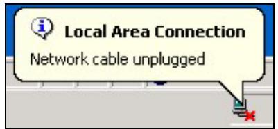
text_image
Local Area Connection Network cable unpluggedFigure 13-10 Network Temporarily Disconnected
After two minutes, log in again and check your new firmware version in the System Status screen.
If the upload was not successful, the following screen will appear. Click Back to go back to the Firmware screen.
Error Message:
ERROR: FAIL TO UPDATE DUE TO... The uploaded file was not accepted by the router.
Back
Figure 13-11 Error Message
Part VII:
SMT General Configuration
This part covers System Management Terminal configuration for general setup, LAN setup, wireless LAN setup, Internet access, remote nodes, remote node TCP/IP, static routing and NAT.
See the web configurator parts of this guide for background information on features configurable by web configurator and SMT.
Chapter 14
Introducing the SMT
This chapter explains how to access and navigate the System Management Terminal and gives an overview of its menus.
14.1 SMT Introduction
The Prestige's SMT (System Management Terminal) is a menu-driven interface that you can access from a terminal emulator through the console port or over a telnet connection.
14.1.1 Procedure for SMT Configuration via Console Port
Follow the steps below to access your Prestige via the console port.
Configure a terminal emulation communications program as follows: VT100 terminal emulation, no parity, 8 data bits, 1 stop bit, data flow set to none, 9600 bps port speed.
Press [ENTER] to display the SMT password screen. The default password is “1234”.
14.1.2 Procedure for SMT Configuration via Telnet
The following procedure details how to telnet into your Prestige.
Step 1. In Windows, click Start (usually in the bottom left corner), Run and then type “telnet 192.168.1.1” (the default IP address) and click OK.
Step 2. Enter "1234" in the Password field.
Step 3. After entering the password you will see the main menu.
Please note that if there is no activity for longer than five minutes (default timeout period) after you log in, your Prestige will automatically log you out. You will then have to telnet into the Prestige again.
14.1.3 Entering Password
The login screen appears after you press [ENTER], prompting you to enter the password, as shown next.
For your first login, enter the default password “1234”. As you type the password, the screen displays an asterisk “*” for each character you type.
Please note that if there is no activity for longer than five minutes after you log in, your Prestige will automatically log you out.
Enter Password : ****
Figure 14-1 Login Screen
14.1.4 Prestige SMT Menu Overview
We use the Prestige 650HW-31 SMT menus in this guide as an example. The SMT menus vary slightly for different Prestige models.
The following figure gives you an overview of the various SMT menu screens of your Prestige.
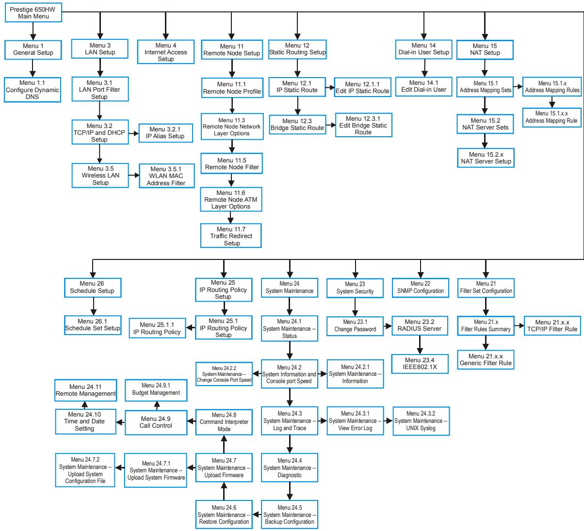
flowchart
graph TD
    A["Prestige 650HW Main Menu"] --> B["Menu 1 General Setup"]
    B --> C["Menu 1.1 Configure Dynamic DNS"]
    C --> D["Menu 3.1 LAN Port Filter Setup"]
    D --> E["Menu 3.2 TCP/IP and DHCP Setup"]
    E --> F["Menu 3.5 Wireless LAN Setup"]
    F --> G["Menu 3.5.1 WLAN MAC Address Filter"]

    A --> H["Menu 3 LAN Setup"]
    H --> I["Menu 4 Internet Access Setup"]
    I --> J["Menu 11 Remote Node Setup"]
    J --> K["Menu 11.1 Remote Node Profile"]
    K --> L["Menu 11.3 Remote Node Network Layer Options"]
    L --> M["Menu 11.5 Remote Node Filter"]
    M --> N["Menu 11.6 Remote Node ATM Layer Options"]
    N --> O["Menu 11.7 Traffic Redirect Setup"]

    A --> P["Menu 12 Static Routing Setup"]
    P --> Q["Menu 12.1 IP Static Route"]
    Q --> R["Menu 12.3 Bridge Static Route"]
    R --> S["Menu 12.3.1 Edit Bridge Static Route"]
    S --> T["Menu 12.1.1 Edit IP Static Route"]
    T --> U["Menu 12.3.1 Edit IP Static Route"]

    A --> V["Menu 14 Dial-in User Setup"]
    V --> W["Menu 14.1 Edit Dial-in User"]
    W --> X["Menu 15.1 Address Mapping Sets"]
    X --> Y["Menu 15.2 NAT Server Sets"]
    Y --> Z["Menu 15.2.x NAT Server Setup"]

    A --> AA["Menu 15 NAT Setup"]
    AA --> AB["Menu 15.1.x Address Mapping Rules"]
    AB --> AC["Menu 15.1.x.x Address Mapping Rule"]

    subgraph System Maintenance
        AD["Menu 26 Schedule Setup"] --> AE["Menu 25 IP Routing Policy Setup"] --> AF["Menu 24 System Maintenance"] --> AG["Menu 23 System Security"] --> AH["Menu 22 SNMP Configuration"] --> AI["Menu 21 Filter Set Configuration"] --> AJ["Menu 21.x.x TCP/IP Filter Rule"] --> AK["Menu 21.x.x Generic Filter Rule"]

    AL["Menu 26.1 Schedule Set Setup"] --> AM["Menu 25.1 IP Routing Policy Setup"] --> AN["Menu 24.1 System Maintenance -- Status"] --> AO["Menu 23.1 Change Password"] --> AP["Menu 23.2 RADIUS Server"] --> AQ["Menu 23.4 IEEE802.1X"] --> AR["Menu 24.1 x Filter Rules Summary"] --> AS["Menu 24.9 x Generic Filter Rule"] --> AT["Menu 24.9.1 Budget Management"] --> AU["Menu 24.8 Command Interpreter Mode"] --> AV["Menu 24.7 System Maintenance -- Upload Firmware"] --> AW["Menu 24.7 System Maintenance -- Upload Firmware"] --> AX["Menu 24.6 System Maintenance -- Restore Configuration"] --> AY["Menu 24.5 System Maintenance -- Backup Configuration"]

    subgraph System Maintenance
        AZ["Menu 24.2 System Maintenance -- Change Console Port Speed"] --> BA["Menu 24.2 System Information and Console port Speed"] --> BB["Menu 24.2.1 System Maintenance -- Information"] --> BC["Menu 24.3 System Maintenance -- Log and Trace"] --> BD["Menu 24.3.1 System Maintenance -- View Error Log"] --> BE["Menu 24.3.2 System Maintenance -- UNIX Syslog"] --> BF["Menu 24.6 System Maintenance -- Restore Configuration"] --> BG["Menu 24.7 System Maintenance -- Upload Firmware"] --> BH["Menu 24.7 System Maintenance -- Upload Firmware"] --> BI["Menu 24.8 Command Interpreter Mode"] --> BJ["Menu 24.8 System Maintenance -- Log and Trace"] --> BK["Menu 24.8 System Maintenance -- Diagnostic"] --> BL["Menu 24.8 System Maintenance -- Diagnostic"]
    end
Figure 14-2 Prestige 650HW-31 SMT Menu Overview
14.2 Navigating the SMT Interface
The SMT (System Management Terminal) is the interface that you use to configure your Prestige.
Several operations that you should be familiar with before you attempt to modify the configuration are listed in the table below.
Table 14-1 Main Menu Commands
| OPERATION | KEYSTROKE | DESCRIPTION |
| Move down to another menu | [ENTER] | To move forward to a submenu, type in the number of the desired submenu and press [ENTER]. |
| Move up to a previous menu | [ESC] | Press [ESC] to move back to the previous menu. |
| Move to a “hidden” menu | Press [SPACE BAR] to change No to Yes then press [ENTER]. | Fields beginning with “Edit” lead to hidden menus and have a default setting of No. Press [SPACE BAR] once to change No to Yes, then press [ENTER] to go to the “hidden” menu. |
| Move the cursor | [ENTER] or [UP]/[DOWN] arrow keys. | Within a menu, press [ENTER] to move to the next field. You can also use the [UP]/[DOWN] arrow keys to move to the previous and the next field, respectively. |
| Entering information | Type in or press [SPACE BAR], then press [ENTER]. | You need to fill in two types of fields. The first requires you to type in the appropriate information. The second allows you to cycle through the available choices by pressing [SPACE BAR]. |
| Required fields | <? > or ChangeMe | All fields with the symbol <?> must be filled in order to be able to save the new configuration.All fields with ChangeMe must not be left blank in order to be able to save the new configuration. |
| N/A fields | Some of the fields in the SMT will show a. This symbol refers to an option that is Not Applicable. | |
| Save your configuration | [ENTER] | Save your configuration by pressing [ENTER] at the message “Press ENTER to confirm or ESC to cancel”. Saving the data on the screen will take you, in most cases to the previous menu. |
| Exit the SMT | Type 99, then press [ENTER]. | Type 99 at the main menu prompt and press [ENTER] to exit the SMT interface. |
After you enter the password, the SMT displays the main menu, as shown next.
Copyright (c) 1994 - 2003 ZyXEL Communications Corp.
Prestige 650HW-31 Main Menu
Getting Started
- General Setup
- LAN Setup
- Internet Access Setup
Advanced Applications
- Remote Node Setup
- Static Routing Setup
- Dial-in User Setup
- NAT Setup
Advanced Management
- Filter Set Configuration
- SNMP Configuration
- System Security
- System Maintenance
- IP Routing Policy Setup
-
Schedule Setup
-
Exit
Enter Menu Selection Number:
Figure 14-3 SMT Main Menu for P650HW
14.2.1 System Management Terminal Interface Summary
Table 14-2 Main Menu Summary for P650HW
| # | MENU TITLE | DESCRIPTION |
| 1 | General Setup | Use this menu to set up your general information. |
| 3 | LAN Setup | Use this menu to set up your wireless LAN (Prestige 650H/HW only) and LAN connection. |
| 4 | Internet Access Setup | A quick and easy way to set up an Internet connection. |
| 11 | Remote Node Setup | Use this menu to set up the Remote Node for LAN-to-LAN connection, including Internet connection. |
| 12 | Static Routing Setup | Use this menu to set up static routes. |
| 14 | Dial-in User Setup | Use this menu to set up local user profiles on the Prestige 650H/HW. |
| 15 | NAT Setup | Use this menu to specify inside servers when NAT is enabled. |
| 21 | Filter Set Configuration | Use this menu to set up filters to provide security, etc. |
| 22 | SNMP Configuration | Use this menu to set up SNMP related parameters. |
| 23 | System Security | Use this menu to set up wireless security (Prestige 650H/HW only) and change your password. |
| 24 | System Maintenance | This menu provides system status, diagnostics, software upload, etc. |
Table 14-2 Main Menu Summary for P650HW
| # | MENU TITLE | DESCRIPTION |
| 25 | IP Routing Policy Setup | Use this menu to configure your IP routing policy. |
| 26 | Schedule Setup | Use this menu to schedule outgoing calls. |
| 99 | Exit | Use this to exit from SMT and return to a blank screen. |
14.3 Changing the System Password
Change the Prestige default password by following the steps shown next.
Step 1. Enter 23 in the main menu to display Menu 23 - System Security.
Step 2. Enter 1 to display Menu 23.1 - System Security - Change Password as shown next.
Step 3. Type your existing system password in the Old Password field, for example “1234”, and press [ENTER].
Menu 23.1 - System Security - Change Password
Old Password= ?
New Password= ?
Retype to confirm= ?
Enter here to CONFIRM or ESC to CANCEL:
Figure 14-4 Menu 23 System Password
Step 4. Type your new system password in the New Password field (up to 30 characters), and press [ENTER].
Step 5. Re-type your new system password in the Retype to confirm field for confirmation and press [ENTER].
Note that as you type a password, the screen displays an “*” for each character you type.
Chapter 15
General Setup
Menu 1 - General Setup contains administrative and system-related information.
15.1 General Setup
Menu 1 — General Setup contains administrative and system-related information (shown next). The System Name field is for identification purposes. However, because some ISPs check this name you should enter your computer's "Computer Name".
- In Windows 95/98 click Start, Settings, Control Panel, Network. Click the Identification tab, note the entry for the Computer name field and enter it as the Prestige System Name.
- In Windows 2000 click Start, Settings, Control Panel and then double-click System. Click the Network Identification tab and then the Properties button. Note the entry for the Computer name field and enter it as the Prestige System Name.
- In Windows XP, click start, My Computer, View system information and then click the Computer Name tab. Note the entry in the Full computer name field and enter it as the Prestige System Name.
The Domain Name entry is what is propagated to the DHCP clients on the LAN. If you leave this blank, the domain name obtained by DHCP from the ISP is used. While you must enter the host name (System Name) on each individual computer, the domain name can be assigned from the Prestige via DHCP.
15.2 Configuring Menu 1
Enter 1 in the Main Menu to open Menu 1 — General Setup (shown next).
Menu 1 - General Setup
System Name= ?
Location=
Contact Person's Name=
Domain Name=
Edit Dynamic DNS= No
Route IP= Yes
Bridge= No
Press ENTER to Confirm or ESC to Cancel:
Figure 15-1 Menu 1 General Setup
Fill in the required fields. Refer to the table shown next for more information about these fields.
Table 15-1 Menu 1 General Setup
| FIELD | DESCRIPTION | EXAMPLE |
| System Name | Enter a descriptive name for identification purposes. This name can be up to 30 alphanumeric characters long. Spaces are not allowed, but dashes “-” and underscores ”_” are accepted. | |
| Location (optional) | Enter the geographic location (up to 31 characters) of your Prestige. | MyHouse |
| Contact Person's Name (optional) | Enter the name (up to 30 characters) of the person in charge of this Prestige. | JohnDoe |
| Domain Name | Enter the domain name (if you know it) here. If you leave this field blank, the ISP may assign a domain name via DHCP. You can go to menu 24.8 and type "sys domainname" to see the current domain name used by your gateway.If you want to clear this field just press the [SPACE BAR]. The domain name entered by you is given priority over the ISP assigned domain name. | zyxel.com.tw |
| Edit Dynamic DNS | Press the [SPACE BAR] to select Yes or No (default). Select Yes to configure Menu 1.1 — Configure Dynamic DNS (discussed next). | No |
| Route IP | Set this field to Yes to enable or No to disable IP routing. You must enable IP routing for Internet access. | Yes |
| Bridge | Turn on/off bridging for protocols not supported (for example, SNA) or not turned on in the previous Route IP field. Select Yes to turn bridging on; select No to turn bridging off. | No |
15.2.1 Configuring Dynamic DNS
If you have a private WAN IP address, then you cannot use Dynamic DNS.
To configure Dynamic DNS, go to Menu 1 — General Setup and select Yes in the Edit Dynamic DNS field. Press [ENTER] to display Menu 1.1— Configure Dynamic DNS as shown next.
Menu 1.1 - Configure Dynamic DNS
Service Provider = WWW.DynDNS.ORG
Active= Yes
Host= me.ddns.org
EMAIL= mail@mailserver
USER= username
Password= *********
Enable Wildcard= No
Press ENTER to confirm or ESC to cancel:
Figure 15-2 Menu 1.1 Configure Dynamic DNS
Follow the instructions in the next table to configure Dynamic DNS parameters.
Table 15-2 Menu 1.1 Configure Dynamic DNS
| FIELD | DESCRIPTION | EXAMPLE |
| Service Provider | This is the name of your Dynamic DNS service provider. | WWW.DynDNS.ORG (default) |
| Active | Press [SPACE BAR] to select Yes and then press [ENTER] to make dynamic DNS active. | Yes |
| Host | Enter the domain name assigned to your Prestige by your Dynamic DNS provider. | me.dyndns.org |
| Enter your e-mail address. | mail@mailserver | |
| USER | Enter your user name. | |
| Password | Enter the password assigned to you. | |
| Enable Wildcard | Your Prestige supports DYNDNS Wildcard. Press [SPACE BAR] and then [ENTER] to select Yes or No This field is N/A when you choose DDNS client as your service provider. | No |
| When you have completed this menu, press [ENTER] at the prompt “Press ENTER to Confirm...” to save your configuration, or press [ESC] at any time to cancel. | ||
Chapter 16 LAN Setup
This chapter covers how to configure your wired Local Area Network (LAN) settings.
16.1 LAN Setup
This section describes how to configure the Ethernet using Menu 3 — LAN Setup. From the main menu, enter 3 to display menu 3.
| Menu 3 - LAN Setup |
| 1. LAN Port Filter Setup 2. TCP/IP and DHCP Setup |
| 5. Wireless LAN Setup |
| Enter Menu Selection Number: |
Figure 16-1 Menu 3 LAN Setup
16.1.1 General Ethernet Setup
This menu allows you to specify filter set(s) that you wish to apply to the Ethernet traffic. You seldom need to filter Ethernet traffic; however, the filter sets may be useful to block certain packets, reduce traffic and prevent security breaches.
| Menu 3.1 - LAN Port Filter Setup |
| Input Filter Sets: protocol filters= device filters= Output Filter Sets: protocol filters= device filters= |
| Press ENTER to Confirm or ESC to Cancel: |
Figure 16-2 Menu 3.1 LAN Port Filter Setup
If you need to define filters, please read the Filter Set Configuration chapter first, then return to this menu to define the filter sets.
16.2 Protocol Dependent Ethernet Setup
Depending on the protocols for your applications, you need to configure the respective Ethernet Setup, as outlined below.
- For TCP/IP Ethernet setup refer to the Internet Access Application chapter.
- For bridging Ethernet setup refer to the Bridging Setup chapter.
16.3 TCP/IP Ethernet Setup and DHCP
Use menu 3.2 to configure your Prestige for TCP/IP.
To edit menu 3.2, enter 3 from the main menu to display Menu 3 — Ethernet Setup. When menu 3 appears, press 2 and press [ENTER] to display Menu 3.2 — TCP/IP and DHCP Ethernet Setup, as shown next:
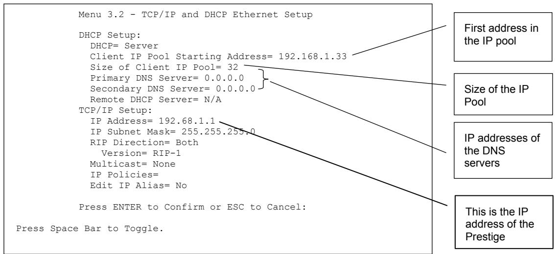
text_image
Menu 3.2 - TCP/IP and DHCP Ethernet Setup DHCP Setup: DHCP= Server Client IP Pool Starting Address= 192.168.1.33 Size of Client IP Pool= 32 Primary DNS Server= 0.0.0.0 Secondary DNS Server= 0.0.0.0 Remote DHCP Server= N/A TCP/IP Setup: IP Address= 192.68.1.1 IP Subnet Mask= 255.255.255.0 RIP Direction= Both Version= RIP-1 Multicast= None IP Policies= Edit IP Alias= No Press ENTER to Confirm or ESC to Cancel: Press Space Bar to Toggle. First address in the IP pool Size of the IP Pool IP addresses of the DNS servers This is the IP address of the PrestigeFigure 16-3 Menu 3.2 TCP/IP and DHCP Ethernet Setup
Follow the instructions in the following table on how to configure the DHCP fields.
Table 16-1 DHCP Ethernet Setup Menu Fields
| FIELD | DESCRIPTION | EXAMPLE |
| DHCP Setup | ||
| DHCP | If set to Server, your Prestige can assign IP addresses, an IP default gateway and DNS servers to Windows 95, Windows NT and other systems that support the DHCP client.If set to None, the DHCP server will be disabled.If set to Relay, the Prestige acts as a surrogate DHCP server and relays DHCP requests and responses between the remote server and the clients. Enter the IP address of the actual, remote DHCP server in the Remote DHCP Server in this case.When DHCP is used, the following items need to be set: | Server (default) |
| Client IP Pool Starting Address | This field specifies the first of the contiguous addresses in the IP address pool. | 192.168.1.33 |
| Size of Client IP Pool | This field specifies the size or count of the IP address pool. | 32 |
| Primary DNS Server Secondary DNS Server | Enter the IP addresses of the DNS servers. The DNS servers are passed to the DHCP clients along with the IP address and the subnet mask. | |
| Remote DHCP Server | If Relay is selected in the DHCP field above then enter the IP address of the actual remote DHCP server here. | |
Follow the instructions in the following table to configure TCP/IP parameters for the Ethernet port.
Table 16-2 TCP/IP Ethernet Setup Menu Fields
| FIELD | DESCRIPTION | EXAMPLE |
| TCP/IP Setup | ||
| IP Address | Enter the (LAN) IP address of your Prestige in dotted decimal notation | 192.168.1.1 |
| IP Subnet Mask | Your Prestige will automatically calculate the subnet mask based on the IP address that you assign. Unless you are implementing subnetting, use the subnet mask computed by the Prestige. | 255.255.255.0 |
| RIP Direction | Press [SPACE BAR] to select the RIP direction. Choices are Both, In Only, Out Only or None. | Both (default) |
| Version | Press [SPACE BAR] to select the RIP version. Choices are RIP-1, RIP-2B or RIP-2M. | RIP-1 (default) |
Table 16-2 TCP/IP Ethernet Setup Menu Fields
| FIELD | DESCRIPTION | EXAMPLE |
| Multicast | IGMP (Internet Group Multicast Protocol) is a network-layer protocol used to establish membership in a Multicast group. The Prestige supports both IGMP version 1 (IGMP-v1) and version 2 (IGMP-v2).Press the [SPACE BAR] to enable IP Multicasting or select None to disable it. | None (default) |
| IP Policies | Create policies using SMT menu 25 (see the IP Policy Routing chapter) and apply them on the Prestige LAN interface here. You can apply up to four IP Policy sets (from twelve) by entering their numbers separated by commas. | 2,4,7,9 |
| Edit IP Alias | The Prestige supports three logical LAN interfaces via its single physical Ethernet interface with the Prestige itself as the gateway for each LAN network. Press [SPACE BAR] to change No to Yes and press [ENTER] to for menu 3.2.1 | No (default) |
Chapter 17
Wireless LAN Setup
This chapter covers how to configure wireless LAN settings in SMT menu 3.5. This chapter is only applicable to the Prestige 650 and Prestige 650HW.
17.1 Wireless LAN Overview
Refer to the chapter on the wireless LAN screens for wireless LAN background information.
17.2 Inserting a PCMCIA Wireless LAN Card
Use a ZyAIR series wireless LAN PCMCIA card to add optional wireless LAN capabilities.
Step 1. Turn off the Prestige.
Never insert or remove a wireless LAN card when the Prestige is turned on.
Step 2. Locate the slot labeled Wireless LAN on the Prestige.
Step 3. With its pin connector facing the slot and the LED side facing upwards, slide the ZyAIR wireless LAN card into the slot.
Never force, bend or twist the wireless LAN card into the slot.
Step 4. Turn on the Prestige. The WLAN LED should turn on.
17.3 Wireless LAN Setup
Use menu 3.5 to set up your Prestige as the wireless access point. To edit menu 3.5, enter 3 from the main menu to display Menu 3 – LAN Setup. When menu 3 appears, press 5 and then press [ENTER] to display Menu 3.5 – Wireless LAN Setup as shown next.
Menu 3.5- Wireless LAN Setup
ESSID= Wireless
Hide ESSIS = No
Channel ID= CH01 2412MHz
RTS Threshold= 2432
Frag. Threshold= 2432
WEP= Disable
    Default Key= N/A
    Key1= N/A
    Key2= N/A
    Key3= N/A
    Key4= N/A
Edit MAC Address Filter= No
Press ENTER to Confirm or ESC to Cancel:
Figure 17-1 Menu 3.5 - Wireless LAN Setup
The following table describes the fields in this menu.
Table 17-1 Wireless LAN Setup Field Description
| FIELD | DESCRIPTION | EXAMPLE |
| ESSID | The ESSID (Extended Service Set IDentifier) identifies the service set the wireless station is to connect to. Wireless stations associating to the Access Point must have the same ESSID. Enter a descriptive name (up to 32 characters) for the wireless Service Set. | Wireless |
| Hide ESSID | Press [SPACE BAR] and select Yes to hide the ESSID in the outgoing beacon frame so a station cannot obtain the ESSID through passive scanning. | No |
| Channel ID | Press [SPACE BAR] to select a channel. This allows you to set the operating frequency/channel depending on your particular region. | CH012412MHz |
| RTSThreshold | RTS(Request To Send) threshold (number of bytes) enables RTS/CTS handshake. Data with its frame size larger than this value will perform the RTS/CTS handshake. Setting this attribute to be larger than the maximum MSDU (MAC Service Data Unit) size turns off the RTS/CTS handshake. Setting this attribute to zero turns on the RTS/CTS handshake. Enter a value between 0 and 2432. | 2432 |
| Frag.Threshold | The threshold (number of bytes) for the fragmentation boundary for directed messages. It is the maximum data fragment size that can be sent. Enter a value between 256 and 2432. | 2432 |
Table 17-1 Wireless LAN Setup Field Description
| FIELD | DESCRIPTION | EXAMPLE |
| WEP | WEP (Wired Equivalent Privacy) provides data encryption to prevent wireless stations from accessing data transmitted over the wireless network.Select Disable allows wireless stations to communicate with the access points without any data encryption.Select 64-bit WEP or 128-bit WEP to for the type of data encryption. WEP causes performance degradation. | Disable |
| Default Key | Enter the number of the key as an active key. | |
| Key 1 to Key 4 | If you chose 64-bit WEP in the WEP Encryption field, then enter 5 characters or 10 hexadecimal digits ("0-9", "A-F") preceded by 0x for each key (1-4).If you chose 128-bit WEP in the WEP Encryption field, then enter 13 characters or 26 hexadecimal digits ("0-9", "A-F") preceded by 0x for each key (1-4).There are four data encryption keys to secure your data from eavesdropping by unauthorized wireless users. The values for the keys must be set up exactly the same on the access points as they are on the wireless station computers. | |
| Edit MAC Address Filter | To edit MAC address filtering table, press [SPACE BAR] to select Yes and press [ENTER] to open menu 3.5.1. | No |
| When you have completed this menu, press [ENTER] at the prompt “Press ENTER to confirm or ESC to cancel” to save your configuration or press [ESC] to cancel and go back to the previous screen. | ||
17.3.1 Wireless LAN MAC Address Filter
The next layer of security is MAC address filter. To allow a wireless station to associate with the Prestige, enter the MAC address of the wireless LAN card on that wireless station in the MAC address table.
| Menu 3.5.1 - WLAN MAC Address Filter | |||||
| Active= No Filter Action= Allowed Association | |||||
| 1= | 00:00:00:00:00:00 | 13= | 00:00:00:00:00:00 | 25= | 00:00:00:00:00:00 |
| 2= | 00:00:00:00:00:00 | 14= | 00:00:00:00:00:00 | 26= | 00:00:00:00:00:00 |
| 3= | 00:00:00:00:00:00 | 15= | 00:00:00:00:00:00 | 27= | 00:00:00:00:00:00 |
| 4= | 00:00:00:00:00:00 | 16= | 00:00:00:00:00:00 | 28= | 00:00:00:00:00:00 |
| 5= | 00:00:00:00:00:00 | 17= | 00:00:00:00:00:00 | 29= | 00:00:00:00:00:00 |
| 6= | 00:00:00:00:00:00 | 18= | 00:00:00:00:00:00 | 30= | 00:00:00:00:00:00 |
| 7= | 19 = | 19 = | 19 = 19 = | 31= | 19 = 19 = |
| 8= | 21 = | 21 = | 21 = | ||
| 9= | 22 = | 22 = | 22 = | ||
| 11= | 23 = | 23 = | 23 = | ||
| 12= | 24 = | 24 = | 24 = | ||
Figure 17-2 Menu 3.5.1 WLAN MAC Address Filtering
The following table describes the fields in this menu.
Table 17-2 Menu 3.5.1 WLAN MAC Address Filtering
| FIELD | DESCRIPTION |
| Active | To enable MAC address filtering, press [SPACE BAR] to select Yes and press [ENTER]. |
| Filter Action | Define the filter action for the list of MAC addresses in the MAC address filter table.To deny access to the Prestige, press [SPACE BAR] to select Deny Association and press [ENTER]. MAC addresses not listed will be allowed to access the router.The default action, Allowed Association, permits association with the Prestige. MAC addresses not listed will be denied access to the router. |
| MAC Address Filter | |
| Address 1.... | Enter the MAC addresses (in XX:XX:XX:XX:XX:XX format) of the wireless station that are allowed or denied access to the Prestige in these address fields. |
| When you have completed this menu, press [ENTER] at the prompt “Press ENTER to confirm or ESC to cancel” to save your configuration or press [ESC] to cancel and go back to the previous screen. | |
Chapter 18
Internet Access
This chapter shows you how to configure the LAN and WAN of your Prestige for Internet access.
18.1 Internet Access Overview
Refer to the chapters on the web configurator's wizard, LAN and WAN screens for more background information on fields in the SMT screens covered in this chapter.
18.2 IP Policies
Traditionally, routing is based on the destination address only and the router takes the shortest path to forward a packet. IP Policy Routing (IPPR) provides a mechanism to override the default routing behavior and alter the packet forwarding based on the policy defined by the network administrator. Policy-based routing is applied to incoming packets on a per interface basis, prior to the normal routing. Create policies using SMT menu 25 (see IP Policy Routing) and apply them on the Prestige LAN and/or WAN interfaces using menus 3.2 (LAN) and 11.3 (WAN).
18.3 IP Alias
IP Alias allows you to partition a physical network into different logical networks over the same Ethernet interface. The Prestige supports three logical LAN interfaces via its single physical Ethernet interface with the Prestige itself as the gateway for each LAN network.
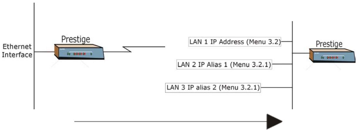
flowchart
graph LR
    A["Ethernet Interface"] --> B["Prestige"]
    B --> C["LAN 1 IP Address (Menu 3.2)"]
    B --> D["LAN 2 IP Alias 1 (Menu 3.2.1)"]
    B --> E["LAN 3 IP alias 2 (Menu 3.2.1)"]
    F["Prestige"] --> G["Output"]
Figure 18-1 Physical Network
Figure 18-2 Partitioned Logical Networks
Use menu 3.2.1 to configure IP Alias on your Prestige.
18.4 IP Alias Setup
Use menu 3.2 to configure the first network. Move the cursor to Edit IP Alias field and press [SPACEBAR] to choose Yes and press [ENTER] to configure the second and third network.
Menu 3.2 - TCP/IP and DHCP Setup
DHCP Setup:
DHCP= Server
Client IP Pool Starting Addres= 192.168.1.33
Size of Client IP Pool= 32
Primary DNS Server= 0.0.0.0
Secondary DNS Server= 0.0.0.0
Remote DHCP Server= N/A
TCP/IP Setup:
IP Address= 192.168.1.1
IP Subnet Mask= 255.255.255.0
RIP Direction= None
Version= N/A
Multicast= None
IP Policies=
Edit IP Alias= Yes

Press ENTER to confirm or ESC to Cancel:
Press Space Bar to Toggle.
Figure 18-3 Menu 3.2 TCP/IP and DHCP Setup
Pressing [ENTER] displays Menu 3.2.1 — IP Alias Setup, as shown next.
Menu 3.2.1 - IP Alias Setup
IP Alias 1= No
    IP Address= N/A
    IP Subnet Mask= N/A
    RIP Direction= N/A
    Version= N/A
    Incoming protocol filters= N/A
    Outgoing protocol filters= N/A
IP Alias 2= No
    IP Address= N/A
    IP Subnet Mask= N/A
    RIP Direction= N/A
    Version= N/A
    Incoming protocol filters= N/A
    Outgoing protocol filters= N/A

Enter here to CONFIRM or ESC to CANCEL:
Figure 18-4 Menu 3.2.1 IP Alias Setup
Follow the instructions in the following table to configure IP Alias parameters.
Table 18-1 Menu 3.2.1 IP Alias Setup
| FIELD | DESCRIPTION | EXAMPLE |
| IP Alias | Choose Yes to configure the LAN network for the Prestige. | Yes |
| IP Address | Enter the IP address of your Prestige in dotted decimal notation | 192.168.1.1 |
| IP Subnet Mask | Your Prestige will automatically calculate the subnet mask based on the IP address that you assign. Unless you are implementing subnetting, use the subnet mask computed by the Prestige | 255.255.255.0 |
| RIP Direction | Press [SPACE BAR] to select the RIP direction. Choices are None, Both, In Only or Out Only. | None |
| Version | Press [SPACE BAR] to select the RIP version. Choices are RIP-1, RIP-2B or RIP-2M. | RIP-1 |
| Incoming Protocol Filters | Enter the filter set(s) you wish to apply to the incoming traffic between this node and the Prestige. | |
| Outgoing Protocol Filters | Enter the filter set(s) you wish to apply to the outgoing traffic between this node and the Prestige. | |
| When you have completed this menu, press [ENTER] at the prompt “Press ENTER to Confirm...” to save your configuration, or press [ESC] at any time to cancel. | ||
18.5 Route IP Setup
The first step is to enable the IP routing in Menu 1 — General Setup.
To edit menu 1, type in 1 in the main menu and press [ENTER]. Set the Route IP field to Yes by pressing [SPACE BAR].
Menu 1 - General Setup
System Name= P650HW
Location= location
Contact Person's Name=
Domain Name=
Edit Dynamic DNS= No
Route IP= Yes
Bridge= No
Press ENTER to Confirm or ESC to Cancel:
Figure 18-5 Menu 1 General Setup
18.6 Internet Access Configuration
Menu 4 allows you to enter the Internet Access information in one screen. Menu 4 is actually a simplified setup for one of the remote nodes that you can access in menu 11. Before you configure your Prestige for Internet access, you need to collect your Internet account information.
Use the Internet Account Information table in the Compact Guide/Read Me First/Quick Start Guide to record your Internet account information. Note that if you are using PPPoA or PPPoE encapsulation, then the only ISP information you need is a login name and password. You only need to know the Ethernet Encapsulation Gateway IP address if you are using ENET ENCAP encapsulation.
From the main menu, type 4 to display Menu 4 - Internet Access Setup, as shown next.
Menu 4 - Internet Access Setup
ISP's Name= MyISP
Encapsulation= ENET ENCAP
Multiplexing= LLC-based
VPI #= 8
VCI #= 35
ATM QoS Type= UBR
    Peak Cell Rate (PCR)= 0
    Sustain Cell Rate (SCR)= 0
    Maximum Burst Size (MBS)= 0
My Login= N/A
My Password= N/A
ENET ENCAP Gateway= N/A
IP Address Assignment= Dynamic
    IP Address= N/A
Network Address Translation= SUA Only
    Address Mapping Set= N/A

Press ENTER to Confirm or ESC to Cancel:
Figure 18-6 Menu 4 Internet Access Setup
The following table contains instructions on how to configure your Prestige for Internet access.
Table 18-2 Menu 4 Internet Access Setup
| FIELD | DESCRIPTION | EXAMPLE |
| ISP's Name | Enter the name of your Internet Service Provider. This information is for identification purposes only. | MyISP |
| Encapsulation | Press [SPACE BAR] to select the method of encapsulation used by your ISP. Choices are PPPoE, PPPoA, RFC 1483 or ENET ENCAP. | ENET ENCAP |
Table 18-2 Menu 4 Internet Access Setup
| FIELD | DESCRIPTION | EXAMPLE |
| Multiplexing | Press [SPACE BAR] to select the method of multiplexing used by your ISP. Choices are VC-based or LLC-based. | LLC-based |
| VPI # | Enter the Virtual Path Identifier (VPI) assigned to you. | 8 |
| VCI # | Enter the Virtual Channel Identifier (VCI) assigned to you. | 35 |
| ATM QoS Type | Press [SPACE BAR] and select CBR (Continuous Bit Rate) to specify fixed (always-on) bandwidth. Select UBR (Unspecified Bit Rate) for applications that are non-time sensitive, such as e-mail. Select VBR (Variable Bit Rate) for bursty traffic and bandwidth sharing with other applications. | UBR |
| Peak Cell Rate (PCR) | This is the maximum rate at which the sender can send cells. Type the PCR. | 0 |
| Sustain Cell Rate (SCR)= 0 | Sustained Cell Rate is the mean cell rate of a bursty, on-off traffic source that can be sent at the peak rate, and a parameter for burst-type traffic. Type the SCR; it must be less than the PCR. | 0 |
| Maximum Burst Size (MBS)= 0 | Refers to the maximum number of cells that can be sent at the peak rate. Type the MBS. The MBS must be less than 65535. | 0 |
| My Login | Configure the My Login and My Password fields for PPPoA and PPPoE encapsulation only. Enter the login name that your ISP gives you. If you are using PPPoE encapsulation, then this field must be of the form user@domain where domain identifies your PPPoE service name. | N/A |
| My Password | Enter the password associated with the login name above. | N/A |
| ENET ENCAP Gateway | Enter the gateway IP address supplied by your ISP when you are using ENET ENCAP encapsulation. | N/A |
| Idle Timeout | This value specifies the number of idle seconds that elapse before the Prestige automatically disconnects the PPPoE session. | 0 |
| IP Address Assignment | Press [SPACE BAR] to select Static or Dynamic address assignment. | Dynamic |
| IP Address | Enter the IP address supplied by your ISP if applicable. | N/A |
Table 18-2 Menu 4 Internet Access Setup
| FIELD | DESCRIPTION | EXAMPLE |
| Network Address Translation | Press [SPACE BAR] to select None, SUA Only or Full Feature. Please see the NAT Chapter for more details on the SUA (Single User Account) feature. | SUA Only |
| Address Mapping Set | Type the numbers of mapping sets (1-8) to use with NAT. See the NAT chapter for details. | N/A |
| When you have completed this menu, press [ENTER] at the prompt “Press ENTER to confirm or ESC to cancel” to save your configuration or press [ESC] to cancel and go back to the previous screen. | ||
If all your settings are correct your Prestige should connect automatically to the Internet. If the connection fails, note the error message that you receive on the screen and take the appropriate troubleshooting steps.
Chapter 19
Remote Node Configuration
This chapter covers remote node configuration.
19.1 Remote Node Setup Overview
This section describes the protocol-independent parameters for a remote node. A remote node is required for placing calls to a remote gateway. A remote node represents both the remote gateway and the network behind it across a WAN connection. When you use menu 4 to set up Internet access, you are configuring one of the remote nodes.
You first choose a remote node in Menu 11- Remote Node Setup. You can then edit that node's profile in menu 11.1, as well as configure specific settings in three submenus: edit IP and bridge options in menu 11.3; edit ATM options in menu 11.6; and edit filter sets in menu 11.5.
19.2 Remote Node Setup
This section describes the protocol-independent parameters for a remote node.
19.2.1 Remote Node Profile
To configure a remote node, follow these steps:
Step 1. From the main menu, enter 11 to display Menu 11 - Remote Node Setup.
Step 2. When menu 11 appears, as shown in the following figure, type the number of the remote node that you want to configure.
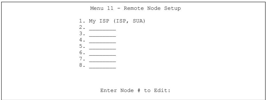
text_image
Menu 11 - Remote Node Setup 1. My ISP (ISP, SUA) 2. ________ 3. ________ 4. ________ 5. ________ 6. ________ 7. ________ 8. ________ Enter Node # to Edit:Figure 19-1 Menu 11 Remote Node Setup
19.2.2 Encapsulation and Multiplexing Scenarios
For Internet access you should use the encapsulation and multiplexing methods used by your ISP. Consult your ISP for information on encapsulation and multiplexing methods for LAN-to-LAN applications, for example between a branch office and corporate headquarters. There must be prior agreement on encapsulation and multiplexing methods because they cannot be automatically determined. What method(s) you use also depends on how many VCs you have and how many different network protocols you need. The extra overhead that ENET ENCAP encapsulation entails makes it a poor choice in a LAN-to-LAN application. Here are some examples of more suitable combinations in such an application.
Scenario 1. One VC, Multiple Protocols
PPPoA (RFC-2364) encapsulation with VC-based multiplexing is the best combination because no extra protocol identifying headers are needed. The PPP protocol already contains this information.
Scenario 2. One VC, One Protocol (IP)
Selecting RFC-1483 encapsulation with VC-based multiplexing requires the least amount of overhead (0 octets). However, if there is a potential need for multiple protocol support in the future, it may be safer to select PPPoA encapsulation instead of RFC-1483, so you do not need to reconfigure either computer later.
Scenario 3. Multiple VCs
If you have an equal number (or more) of VCs than the number of protocols, then select RFC-1483 encapsulation and VC-based multiplexing.
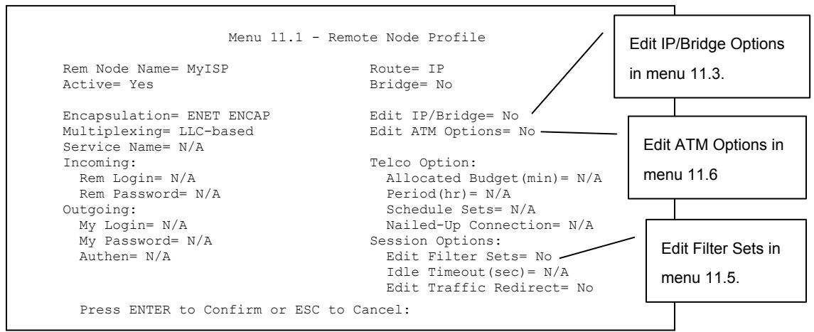
text_image
Menu 11.1 - Remote Node Profile Rem Node Name= MyISP Route= IP Active= Yes Bridge= No Encapsulation= ENET ENCAP Edit IP/Bridge= No Multiplexing= LLC-based Edit ATM Options= No Service Name= N/A Incoming: Telco Option: Rem Login= N/A Allocated Budget(min)= N/A Rem Password= N/A Period(hr)= N/A Outgoing: Schedule Sets= N/A My Login= N/A Nailed-Up Connection= N/A My Password= N/A Session Options: Authen= N/A Edit Filter Sets= No Press ENTER to Confirm or ESC to Cancel: Edit IP/Bridge Options in menu 11.3. Edit ATM Options in menu 11.6 Edit Filter Sets in menu 11.5.Figure 19-2 Menu 11.1 Remote Node Profile
In Menu 11.1 – Remote Node Profile, fill in the fields as described in the following table.
Table 19-1 Menu 11.1 Remote Node Profile
| FIELD | DESCRIPTION | EXAMPLE |
| Rem Node Name | Type a unique, descriptive name of up to eight characters for this node. | MyISP |
| Active | Press [SPACE BAR] and then [ENTER] to select Yes to activate or No to deactivate this node. Inactive nodes are displayed with a minus sign “-” in SMT menu 11. | Yes |
| Encapsulation | PPPoA refers to RFC-2364 (PPP Encapsulation over ATM Adaptation Layer 5).If RFC-1483 (Multiprotocol Encapsulation over ATM Adaptation Layer 5) of ENET ENCAP are selected,then the Rem Login, Rem Password, My Login, My Password and Authen fields are not applicable (N/A). | ENETENCAP |
| Multiplexing | Press [SPACE BAR] and then [ENTER] to select the method of multiplexing that your ISP uses, either VC-based or LLC-based. | LLC-based |
| Service Name | When using PPPoE encapsulation, type the name of your PPPoE service here. | N/A |
| Incoming: |
Table 19-1 Menu 11.1 Remote Node Profile
| FIELD | DESCRIPTION | EXAMPLE |
| Rem Login | Type the login name that this remote node will use to call your Prestige. The login name and the Rem Password will be used to authenticate this node. | |
| Rem Password | Type the password used when this remote node calls your Prestige. | |
| Outgoing: | ||
| My Login | Type the login name assigned by your ISP when the Prestige calls this remote node. | |
| My Password | Type the password assigned by your ISP when the Prestige calls this remote node. | |
| Authen | This field sets the authentication protocol used for outgoing calls. Options for this field are:CHAP/PAP – Your Prestige will accept either CHAP or PAP when requested by this remote node.CHAP – accept CHAP (Challenge Handshake Authentication Protocol) only.PAP – accept PAP (Password Authentication Protocol) only. | |
| Route | This field determines the protocol used in routing. Options are IP and None. | IP |
| Bridge | When bridging is enabled, your Prestige will forward any packet that it does not route to this remote node; otherwise, the packets are discarded. Select Yes to enable and No to disable. | No |
| Edit IP/Bridge | Press [SPACE BAR] to select Yes and press [ENTER] to display Menu 11.3 – Remote Node Network Layer Options. | No |
| Edit ATM Options | Press [SPACE BAR] to select Yes and press [ENTER] to display Menu 11.6 – Remote Node ATM Layer Options. | No |
| Telco Option | ||
| Allocated Budget (min) | This sets a ceiling for outgoing call time for this remote node. The default for this field is 0 meaning no budget control. | |
| Period (hr) | This field is the time period that the budget should be reset. For example, if we are allowed to call this remote node for a maximum of 10 minutes every hour, then the Allocated Budget is (10 minutes) and the Period (hr) is 1 (hour). |
Table 19-1 Menu 11.1 Remote Node Profile
| FIELD | DESCRIPTION | EXAMPLE |
| Schedule Sets | This field is only applicable for PPPoE and PPPoA encapsulation. You can apply up to four schedule sets here. For more details please refer to the Call Scheduling chapter. | |
| Nailed up Connection | This field is only applicable for PPPoE and PPPoA encapsulation. This field specifies if you want to make the connection to this remote node a nailed-up connection. | |
| Session Options | ||
| Edit Filter Sets | Use [SPACE BAR] to choose Yes and press [ENTER] to open menu 11.5 to edit the filter sets. See the Remote Node Filter section for more details. | No (default) |
| Idle Timeout (sec) | Type the number of seconds (0-9999) that can elapse when the Prestige is idle (there is no traffic going to the remote node), before the Prestige automatically disconnects the remote node. 0 means that the session will not timeout. | |
| Edit Traffic Redirect | Use [SPACE BAR] to choose Yes and press [ENTER] to open menu 11.7 to edit the traffic redirect. See the Traffic Redirect section for more details.This field is not available on all models. | No (default) |
| When you have completed this menu, press [ENTER] at the prompt “Press ENTER to confirm or ESC to cancel” to save your configuration or press [ESC] to cancel and go back to the previous screen. | ||
19.2.3 Outgoing Authentication Protocol
For obvious reasons, you should employ the strongest authentication protocol possible. However, some vendors' implementation includes specific authentication protocol in the user profile. It will disconnect if the negotiated protocol is different from that in the user profile, even when the negotiated protocol is stronger than specified. If the peer disconnects right after a successful authentication, make sure that you specify the correct authentication protocol when connecting to such an implementation.
19.3 Metric
The metric represents the "cost of transmission". A router determines the best route for transmission by choosing a path with the lowest "cost". RIP routing uses hop count as the measurement of cost, with a
minimum of "1" for directly connected networks. The number must be between "1" and "15"; a number greater than "15" means the link is down. The smaller the number, the lower the "cost".
The metric sets the priority for the Prestige's routes to the Internet. If any two of the default routes have the same metric, the Prestige uses the following pre-defined priorities:
- Normal route: designated by the ISP
- Traffic-redirect route
IP Policy Routing overrides the default routing behavior and takes priority over all of the routes mentioned above (see the IP Policy Routing chapter).
For example, if the normal route has a metric of "1" and the traffic-redirect route has a metric of "2", then the normal route acts as the primary default route. If the normal route fails to connect to the Internet, the Prestige tries the traffic-redirect route next.
19.4 Remote Node Network Layer Options
For the TCP/IP parameters, perform the following steps to edit Menu 11.3 – Remote Node Network Layer Options as shown next.
Step 1. In menu 11.1, make sure IP is among the protocols in the Route field.
Step 2. Move the cursor to the Edit IP/Bridge field, press [SPACE BAR] to select Yes, then press [ENTER] to display Menu 11.3 – Remote Node Network Layer Options.
Menu 11.3 - Remote Node Network Layer Options
IP Options: Bridge Options:
IP Address Assignment= Dynamic Ethernet Addr Timeout (min)= N/A
Rem IP Addr: 0.0.0.0
Rem Subnet Mask= 0.0.0.0
My WAN Addr= 0.0.0.0
NAT= Full Feature
Address Mapping Set= 2
Metric= 2
Private= No
RIP Direction= None
Version= RIP-1
Multicast= None
IP Policies= 3,4,5,6
Press ENTER to Confirm or ESC to Cancel:
Figure 19-3 Menu 11.3 Remote Node Network Layer Options
The next table explains fields in Menu 11.3 - Remote Node Network Layer Options.
Table 19-2 Menu 11.3 Remote Node Network Layer Options
| FIELD | DESCRIPTION | EXAMPLE |
| IP Address Assignment | Press [SPACE BAR] and then [ENTER] to selectDynamicif the remote node is using a dynamically assigned IP address orStaticif it is using a static (fixed) IP address. You will only be able to configure this in the ISP node (also the one you configure in menu 4). All other nodes are set to Static. | Dynamic |
| Rem IP Addr | This is the IP address you entered in the previous menu. | |
| Rem Subnet Mask | Type the subnet mask assigned to the remote node. | |
| My WAN Addr | Some implementations, especially UNIX derivatives, require separate IP network numbers for the WAN and LAN links and each end to have a unique address within the WAN network number. In that case, type the IP address assigned to the WAN port of your Prestige.NOTE: Refers to local Prestige address, not the remote router address. | |
| NAT | Press [SPACE BAR] and then [ENTER] to selectFull Featureif you have multiple public WAN IP addresses for your Prestige.SelectSUA Onlyif you have just one public WAN IP address for your Prestige. The SMT uses Address Mapping Set 255 (menu 15.1 - see section 22.3.1).Select Noneto disable NAT. | SUA Only |
Table 19-2 Menu 11.3 Remote Node Network Layer Options
| FIELD | DESCRIPTION | EXAMPLE |
| Address Mapping Set | When Full Feature is selected in the NAT field, configure address mapping sets in menu 15.1. Select one of the NAT server sets (2-10) in menu 15.2 (see the NAT chapter for details) and type that number here.When SUA Only is selected in the NAT field, the SMT uses NAT server set 1 in menu 15.2 (see the NAT chapter for details). | 2 |
| Metric | The metric represents the “cost” of transmission for routing purposes. IP routing uses hop count as the cost measurement, with a minimum of 1 for directly connected networks. Type a number that approximates the cost for this link. The number need not be precise, but it must be between 1 and 15. In practice, 2 or 3 is usually a good number. | 2 |
| Private | This determines if the Prestige will include the route to this remote node in its RIP broadcasts. If set to Yes, this route is kept private and not included in RIP broadcast. If No, the route to this remote node will be propagated to other hosts through RIP broadcasts. | No |
| RIP Direction | Press [SPACE BAR] and then [ENTER] to select the RIP Direction. Options are Both, In Only, Out Only or None. | None |
| Version | Press [SPACE BAR] and then [ENTER] to select the RIP version. Options are RIP-1, RIP-2B or RIP-2M. | RIP-1 |
| Multicast | IGMP-v1 sets IGMP to version 1, IGMP-v2 sets IGMP to version 2 and None disables IGMP. | None |
| IP Policies | You can apply up to four IP Policy sets (from 12) by typing in their numbers separated by commas. Configure the filter sets in menu 25 first (see the IP Policy Routing chapter) and then apply them here. | 3, 4, 5, 6 |
| When you have completed this menu, press [ENTER] at the prompt “Press ENTER to confirm or ESC to cancel” to save your configuration or press [ESC] to cancel and go back to the previous screen. | ||
19.4.1 My WAN Addr Sample IP Addresses
The following figure uses sample IP addresses to help you understand the field of My Wan Addr in menu 11.3. Refer to the previous LAN and WAN IP Addresses figure in the web configurator chapter on LAN setup for a brief review of what a WAN IP is. My WAN Addr indicates the local Prestige WAN IP (172.16.0.1 in the following figure) while Rem IP Addr indicates the peer WAN IP (172.16.0.2 in the following figure).
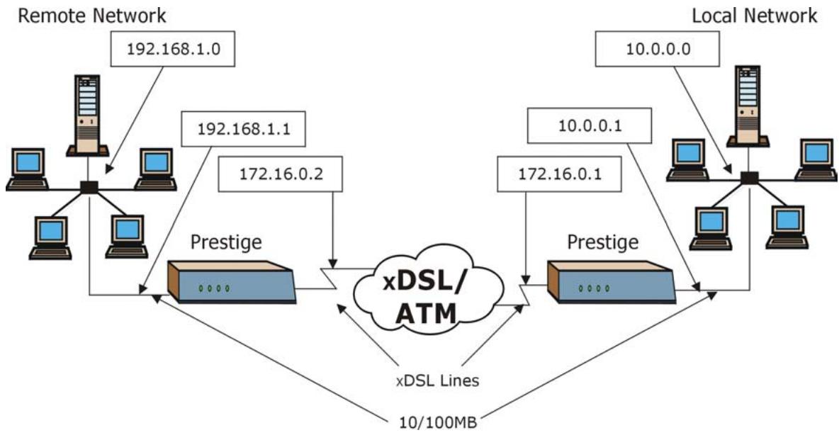
flowchart
graph TD
    A["Remote Network"] -->|192.168.1.0| B["Prestige"]
    A -->|192.168.1.1| B
    A -->|172.16.0.2| B
    C["Local Network"] -->|10.0.0.0| D["Prestige"]
    C -->|10.0.0.1| D
    C -->|172.16.0.1| D
    D --> E["xDSL/ATM"]
    E --> F["xDSL Lines"]
    F --> G["10/100MB"]
    G --> H["Computer"]
    style A fill:#f9f,stroke:#333
    style C fill:#f9f,stroke:#333
    style B fill:#ccf,stroke:#333
    style D fill:#ccf,stroke:#333
    style E fill:#cfc,stroke:#333
    style F fill:#fcc,stroke:#333
    style G fill:#fcc,stroke:#333
Figure 19-4 Sample IP Addresses for a TCP/IP LAN-to-LAN Connection
19.5 Remote Node Filter
Move the cursor to the Edit Filter Sets field in menu 11.1, then press [SPACE BAR] to select Yes. Press [ENTER] to display Menu 11.5 – Remote Node Filter.
Use Menu 11.5 – Remote Node Filter to specify the filter set(s) to apply to the incoming and outgoing traffic between this remote node and the Prestige and also to prevent certain packets from triggering calls. You can specify up to 4 filter sets separated by comma, for example, 1, 5, 9, 12, in each filter field.
Note that spaces are accepted in this field. The Prestige has a prepackaged filter set, NetBIOS_WAN, that blocks NetBIOS packets (call protocol filter = 1). Include this in the call filter sets if you want to prevent NetBIOS packets from triggering calls to a remote node.
Menu 11.5 - Remote Node Filter
Input Filter Sets:
protocol filters= 11, 12
device filters=
Output Filter Sets:
protocol filters=
device filters=
Enter here to CONFIRM or ESC to CANCEL:
Figure 19-5 Menu 11.5 Remote Node Filter (RFC 1483 or ENET Encapsulation)
Menu 11.5 - Remote Node Filter
Input Filter Sets:
protocol filters= 11, 12
device filters=
Output Filter Sets:
protocol filters=
device filters=
Call Filter Sets:
Protocol filters=
Device filters=
Enter here to CONFIRM or ESC to CANCEL:
Figure 19-6 Menu 11.5 Remote Node Filter (PPPoA or PPPoE Encapsulation)
19.5.1 Web Configurator Internet Security Filter Rules
In the web configurator, open the Security screen as shown next. Select the predefined filter rules and click Apply.
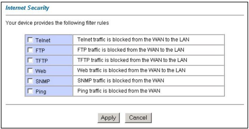
text_image
Internet Security Your device provides the following filter rules Telnet FTP TFTP Web SNMP Ping Telnet traffic is blocked from the WAN to the LAN FTP traffic is blocked from the WAN to the LAN TFTP traffic is blocked from the WAN to the LAN Web traffic is blocked from the WAN to the LAN SNMP traffic is blocked from the WAN Ping traffic is blocked from the WAN Apply CancelFigure 19-7 Internet Security
Once you apply the filter rules in the web configurator, filter sets 11 and 12 are automatically applied in the protocol filters field under Input Filter Sets in SMT menu 11.5.
SMT input protocol filter set numbers that were previously applied are erased after you apply the Internet Security filter rules in the web configurator. To reapply them or apply new filter sets, you need to enter the filter set numbers again along with filter sets 11 and 12. For example, to apply filter sets 1 and 2, you enter “1, 2, 11, 12”.
19.5.2 Web Configurator Filter Sets
When you apply filter rules using the web configurator, filter sets 11 and 12 are automatically generated in SMT menu 21.
| Menu 21 - Filter Set Configuration | |||
| Filter Set # | Comments | Filter Set # | Comments |
| 1 | 7 | ||
| 2 | NetBIOS_WAN | 8 | |
| 3 | NetBIOS_LAN | 9 | |
| 4 | IGMP | 10 | |
| 5 | 11 | WebSet1 | |
| 6 | 12 | WebSet2 | |
| Enter Filter Set Number to Configure= 0 | |||
Figure 19-8 Menu 21- Filer Set Configuration (P650H/HW)
The following figures display the filter rules in filter sets 11 and 12.
| Menu 21.11 - Filter Rules Summary | |||
| # A Type | Filter Rules | M m n | |
| - - - - - - - - - - - - - - - - - - - - - - - - - - - - - - - - - - - - - - - - - - - - - - - - - - - - - - - - - - - - - - - - - - - - - - - - - - - - - - - - - - - - - - - - - | |||
| 1 Y IP | Pr=17, SA=0.0.0.0, DA=0.0.0.0, DP=161 | N D N | |
| 2 Y IP | Pr=17, SA=0.0.0.0, DA=0.0.0.0, DP=162 | N D F | |
| 3 N | |||
| 4 N | |||
| 5 N | |||
| 6 N | |||
| Enter Filter Rule Number (1-6) to Configure: | |||
Figure 19-9 Menu 21.11- WebSet 11
| Menu 21.12 - Filter Rules Summary | |||
| # A Type | Filter Rules | M m n | |
| - - - - - - - - - - - - - - - - - - - - - - - - - - - - - - - - - - - - - - - - - - - - - - - - - - - - - - - - - - - - - - - - - - - - - - - - - - - - - - - - - - - - - - - | |||
| 1 Y IP | Pr=6, SA=0.0.0.0, DA=0.0.0.0, DP=23 | N D N | |
| 2 Y IP | Pr=6, SA=0.0.0.0, DA=0.0.0.0, DP=21 | N D N | |
| 3 Y IP | Pr=17, SA=0.0.0.0, DA=0.0.0.0, DP=69 | N D N | |
| 4 Y IP | Pr=6, SA=0.0.0.0, DA=0.0.0.0, DP=80 | N D N | |
| 5 Y IP | Pr=1, SA=0.0.0.0, DA=0.0.0.0, DP=0 | N D N | |
| 6 N | |||
| Enter Filter Rule Number (1-6) to Configure | |||
Figure 19-10 Menu 21.12- WebSet 12
Do not edit filter sets 11 and 12. They are used exclusively by the web configurator. Any rules you configured in sets 11 and 12 will be erased and replaced when you apply the web configurator-generated filter rules.
19.6 Editing ATM Layer Options
Follow the steps shown next to edit Menu 11.6 – Remote Node ATM Layer Options.
In menu 11.1, move the cursor to the Edit ATM Options field and then press [SPACE BAR] to select Yes. Press [ENTER] to display Menu 11.6 – Remote Node ATM Layer Options.
There are two versions of menu 11.6 for the Prestige, depending on whether you chose VC-based/LLC-based multiplexing and PPP encapsulation in menu 11.1.
19.6.1 VC-based Multiplexing (non-PPP Encapsulation)
For VC-based multiplexing, by prior agreement, a protocol is assigned a specific virtual circuit, for example, VC1 will carry IP. Separate VPI and VCI numbers must be specified for each protocol.
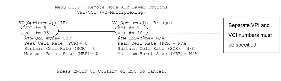
text_image
Menu 11.6 - Remote Node ATM Layer Options VPI/VCI (VC-Multiplexing) VC Options for IP: VPI # = 8 VCI # = 35 ATM QoS Type= UBR Peak Cell Rate (PCR)= 0 Sustain Cell Rate (SCR)= 0 Maximum Burst Size (MBS)= 0 VC Options for Bridge: VPI # = 1 VCI # = 36 ATM QoS Type= N/A Peak Cell Rate (PCR)= N/A Sustain Cell Rate (SCR)= N/A Maximum Burst Size (MBR)= N/A Press ENTER to Confirm or ESC to Cancel: Separate VPI and VCI numbers must be specified.Figure 19-11 Menu 11.6 for VC-based Multiplexing
19.6.2 LLC-based Multiplexing or PPP Encapsulation
For LLC-based multiplexing or PPP encapsulation, one VC carries multiple protocols with protocol identifying information being contained in each packet header.
Menu 11.6 - Remote Node ATM Layer Options
VPI/VCI (LLC-Multiplexing or PPP-Encapsulation)
VPI #= 8
VCI #= 35
ATM QoS Type= UBR
Peak Cell Rate (PCR)= 0
Sustain Cell Rate (SCR)= 0
Maximum Burst Size (MBS)= 0
ENTER here to CONFIRM or ESC to CANCEL:
Only one set of VPI and VCI numbers needs to be specified.
Figure 19-12 Menu 11.6 for LLC-based Multiplexing or PPP Encapsulation
In this case, only one set of VPI and VCI numbers need be specified for all protocols. The valid range for the VPI is 0 to 255 and for the VCI is 32 to 65535 (1 to 31 is reserved for local management of ATM traffic).
19.7 Traffic Redirect
Traffic redirect forwards LAN traffic to a backup gateway when the Prestige cannot connect to the Internet. An example is shown in the figure below.
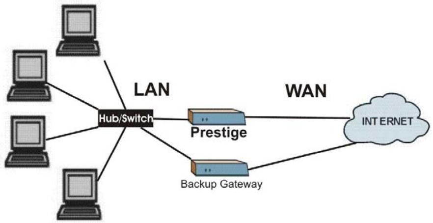
flowchart
graph TD
    A["Client 1"] --> B["Hub/Switch"]
    C["Client 2"] --> B
    D["Client 3"] --> B
    E["Client 4"] --> B
    B --> F["Prestige"]
    B --> G["Backup Gateway"]
    F --> H["INTERNET"]
    G --> H
    I["LAN"] --> B
    J["WAN"] --> H
Figure 19-13 Traffic Redirect Setup Example
To configure the parameters for traffic redirect, enter 11 from the main menu to display Menu 11.1-Remote Node Profile as shown next.
Menu 11.1 - Remote Node Profile
Rem Node Name= MyISP Route= IP
Active= Yes Bridge= No
Encapsulation= ENET ENCAP Edit IP/Bridge= No
Multiplexing= LLC-based Edit ATM Options= No
Service Name= N/A
Incoming: Telco Option:
Rem Login= N/A Allocated Budget(min)= N/A
Rem Password= N/A Period(hr)= N/A
Outgoing: Schedule Sets= N/A
My Login= N/A Nailed-Up Connection= N/A
My Password= N/A Session Options:
Authen= N/A Edit Filter Sets= No
Idle Timeout(sec)= N/A
Edit Traffic Redirect= Yes
Press ENTER to Confirm or ESC to Cancel:
Figure 19-14 Menu 11.1 – Remote Node Profile
To configure traffic redirect properties, press [SPACE BAR] to select Yes in the Edit Traffic Redirect field and then press [ENTER].
Table 19-3 Menu 11.1 – Remote Node Profile (Traffic Redirect Field)
| FIELD | DESCRIPTION | EXAMPLE |
| Edit Traffic Redirect | Press [SPACE BAR] to select Yes and press [ENTER] to configure Menu 11.7 – Traffic Redirect Setup. | Yes |
| Press [ENTER] at the message “Press ENTER to Confirm...” to save your configuration, or press [ESC] at any time to cancel. | ||
19.7.1 Traffic Redirect Setup
Configure parameters that determine when the Prestige will forward WAN traffic to the backup gateway using Menu 11.7 — Traffic Redirect Setup.
Menu 11.7 - Traffic Redirect Setup
Active= No
Configuration:
Backup Gateway IP Address= 0.0.0.0
Metric= 15
Press ENTER to Confirm or ESC to Cancel:
Figure 19-15 Menu 11.7 Traffic Redirect Setup
The following table describes the fields in this menu.
Table 19-4 Menu 11.7 Traffic Redirect Setup
| FIELD | DESCRIPTION |
| Active | Press [SPACE BAR] and select Yes (to enable) or No (to disable) traffic redirect setup. The default is No.When the Active field is Yes, you must configure every field in this screen unless you are using PPPoE encapsulation (except Check WAN IP Address and Timeout).If you don't configure these fields and are using PPPoE encapsulation, then the Prestige checks the PPPoE channel to determine if the WAN connection is down. |
| Configuration: | |
| Backup Gateway IP Address | Enter the IP address of your backup gateway in dotted decimal notation.The Prestige automatically forwards traffic to this IP address if the Prestige's Internet connection terminates. |
| Metric | This field sets this route's priority among the routes the Prestige uses.The metric represents the "cost of transmission". A router determines the best route for transmission by choosing a path with the lowest "cost". RIP routing uses hop count as the measurement of cost, with a minimum of "1" for directly connected networks. The number must be between "1" and "15"; a number greater than "15" means the link is down. The smaller the number, the lower the "cost". |
| When you have completed this menu, press [ENTER] at the prompt “Press [ENTER] to confirm or [ESC] to cancel” to save your configuration or press [ESC] to cancel and go back to the previous screen. | |
Chapter 20
Static Route Setup
This chapter shows how to setup IP static routes.
20.1 IP Static Route Overview
Static routes tell the Prestige routing information that it cannot learn automatically through other means. This can arise in cases where RIP is disabled on the LAN or a remote network is beyond the one that is directly connected to a remote node.
Each remote node specifies only the network to which the gateway is directly connected and the Prestige has no knowledge of the networks beyond. For instance, the Prestige knows about network N2 in the following figure through remote node Router 1. However, the Prestige is unable to route a packet to network N3 because it does not know that there is a route through remote node Router 1 (via Router 2). The static routes allow you to tell the Prestige about the networks beyond the remote nodes.
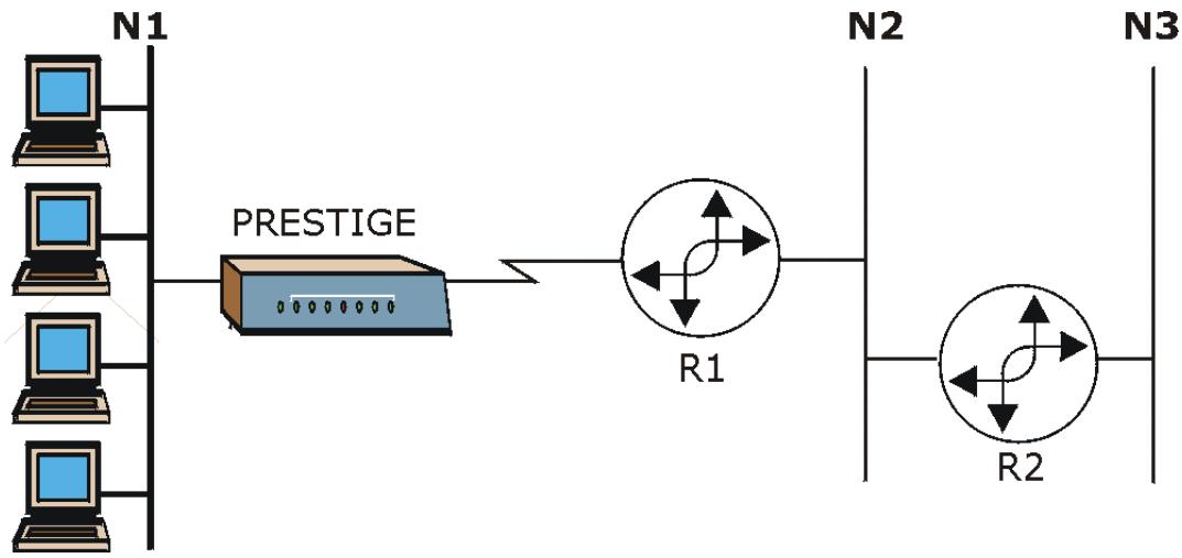
flowchart
graph LR
    N1["Computer 1"] --> PPESTIGE["Prestige"]
    N2["Computer 2"] --> R1["R1"]
    N3["Computer 3"] --> R2["R2"]
    PPESTIGE --> R1
    R1 --> R2
Figure 20-1 Sample Static Routing Topology
20.2 Configuring an IP static route
Step 1. To configure an IP static route, use Menu 12 – Static Route Setup (shown next).
Menu 12 - Static Route Setup
1. IP Static Route
3. Bridge Static Route
Please enter selection:
Figure 20-2 Menu 12 Static Route Setup
Step 2. From menu 12, select 1 to open Menu 12.1 — IP Static Route Setup (shown next).
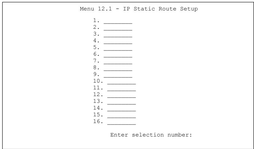
text_image
Menu 12.1 - IP Static Route Setup 1. ________ 2. ________ 3. ________ 4. ________ 5. ________ 6. ________ 7. ________ 8. ________ 9. ________ 10. ________ 11. ________ 12. ________ 13. ________ 14. ________ 15. ________ 16. ________ Enter selection number:Figure 20-3 Menu 12.1 IP Static Route Setup (P650H/HW)
Step 3. Now, type the route number of a static route you want to configure.
Menu 12.1.1 - Edit IP Static Route
Route #: 1
Route Name = ?
Active = No
Destination IP Address = ?
IP Subnet Mask = ?
Gateway IP Address = ?
Metric = 2
Private = No
Press ENTER to Confirm or ESC to Cancel:
Figure 20-4 Menu12.1.1 Edit IP Static Route
The following table describes the fields for Menu 12.1.1 – Edit IP Static Route Setup.
Table 20-1 Menu12.1.1 Edit IP Static Route
| FIELD | DESCRIPTION |
| Route # | This is the index number of the static route that you chose in menu 12.1. |
| Route Name | Type a descriptive name for this route. This is for identification purpose only. |
| Active | This field allows you to activate/deactivate this static route. |
| Destination IP Address | This parameter specifies the IP network address of the final destination. Routing is always based on network number. If you need to specify a route to a single host, use a subnet mask of 255.255.255.255 in the subnet mask field to force the network number to be identical to the host ID. |
| IP Subnet Mask | Type the subnet mask for this destination. Follow the discussion on IP Subnet Mask in this manual. |
| Gateway IP Address | Type the IP address of the gateway. The gateway is an immediate neighbor of your Prestige that will forward the packet to the destination. On the LAN, the gateway must be a router on the same segment as your Prestige; over WAN, the gateway must be the IP address of one of the remote nodes. |
| Metric | Metric represents the “cost” of transmission for routing purposes. IP routing uses hop count as the measurement of cost, with a minimum of 1 for directly connected networks. Type a number that approximates the cost for this link. The number need not be precise, but it must be between 1 and 15. In practice, 2 or 3 is usually a good number. |
Table 20-1 Menu12.1.1 Edit IP Static Route
| FIELD | DESCRIPTION |
| Private | This parameter determines if the Prestige will include the route to this remote node in its RIP broadcasts. If set to Yes, this route is kept private and is not included in RIP broadcasts. If No, the route to this remote node will be propagated to other hosts through RIP broadcasts. |
| When you have completed this menu, press [ENTER] at the prompt “Press ENTER to confirm or ESC to cancel” to save your configuration or press [ESC] to cancel and go back to the previous screen. | |
Chapter 21
Bridging Setup
This chapter shows you how to configure the bridging parameters of your Prestige.
21.1 Bridging Overview
Bridging bases the forwarding decision on the MAC (Media Access Control), or hardware address, while routing does it on the network layer (IP) address. Bridging allows the Prestige to transport packets of network layer protocols that it does not route, for example, SNA, from one network to another. The caveat is that, compared to routing, bridging generates more traffic for the same network layer protocol, and it also demands more CPU cycles and memory.
For efficiency reasons, do not turn on bridging unless you need to support protocols other than IP on your network. For IP, enable the routing if you need it; do not bridge what the Prestige can route.
21.2 Bridge Ethernet Setup
Basically, all non-local packets are bridged to the WAN. Your Prestige does not support IPX.
21.2.1 Remote Node Bridging Setup
Follow the procedure in another section to configure the protocol-independent parameters in Menu 11.1 – Remote Node Profile. For bridging-related parameters, you need to configure Menu 11.3 – Remote Node Network Layer Options.
To setup Menu 11.3 – Remote Node Network Layer Options shown in the next figure, follow these steps:
Step 1. In menu 11.1, make sure the Bridge field is set to Yes.
| Menu 11.1 - Remote Node Profile | |
| Rem Node Name= ? Active= Yes | Route= IP Bridge= Yes |
| Encapsulation= ENET ENCAP Multiplexing= VC-based Service Name= N/A Incoming: Rem Login= N/A Rem Password= N/A Outgoing: My Login= N/A My Password= N/A Authen= N/A | Edit IP/Bridge= Yes Edit ATM Options= No Telco Option: Allocated Budget(min)= N/A Period(hr)= N/A Schedule Sets= N/A Nailed-Up Connection= N/A Session Options: Edit Filter Sets= No Idle Timeout(sec)= N/A Edit Traffic Redirect= No |
| Press ENTER to Confirm or ESC to Cancel: | |
Figure 21-1 Menu 11.1 Remote Node Profile
Step 2. Move the cursor to the Edit IP/Bridge field, then press [SPACE BAR] to set the value to Yes and press [ENTER] to edit Menu 11.3 – Remote Node Network Layer Options.
| Menu 11.3 - Remote Node Network Layer Options | |
| IP Options: | Bridge Options: |
| IP Address Assignment= Static | Ethernet Addr Timeout (min)= 0 |
| Rem IP Addr: 0.0.0.0 | |
| Rem Subnet Mask= 0.0.0.0 | |
| My WAN Addr= 0.0.0.0 | |
| NAT= Full Feature | |
| Address Mapping Set=2 | |
| Metric= 2 | |
| Private= No | |
| RIP Direction= Both | |
| Version= RIP-2B | |
| Multicast= IGMP-v2 | |
| IP Policies= | |
| Press ENTER to Confirm or ESC to Cancel: | |
Figure 21-2 Menu 11.3 Remote Node Network Layer Options
Table 21-1 Menu 11.3 Remote Node Network Layer Options : Bridge Fields
| FIELD | DESCRIPTION |
| Bridge (menu 11.1) | Make sure this field is set to Yes. |
| Edit IP/Bridge (menu 11.1) | Press [SPACE BAR] to select Yes and press [ENTER] to display menu 11.3. |
| Ethernet Addr Timeout (min.) (menu 11.3) | Type the time (in minutes) for the Prestige to retain the Ethernet Address information in its internal tables while the line is down. If this information is retained, your Prestige will not have to recompile the tables when the line comes back up. |
| When you have completed this menu, press [ENTER] at the prompt “Press ENTER to confirm or ESC to cancel” to save your configuration or press [ESC] to cancel and go back to the previous screen. | |
21.2.2 Bridge Static Route Setup
Similar to network layer static routes, a bridging static route tells the Prestige the route to a node before a connection is established. You configure bridge static routes in menu 12.3.1 (go to menu 12, choose option 3, then choose a static route to edit) as shown next.
Menu 12.3 - Bridge Static Route Setup
1. ____
2. ____
3. ____
4. ____
Enter selection number:
Figure 21-3 Menu 12.3 Bridge Static Route Setup
Menu 12.3.1 - Edit Bridge Static Route
Route #: 1
Route Name=
Active= No
Ether Address= ?
IP Address=
Gateway Node= 1
Press ENTER to Confirm or ESC to Cancel:
Figure 21-4 Menu 12.3.1 Edit Bridge Static Route
The following table describes the Edit Bridge Static Route menu.
Table 21-2 Menu 12.3.1 Edit Bridge Static Route
| FIELD | DESCRIPTION |
| Route # | This is the route index number you typed in Menu 12.3 – Bridge Static Route Setup. |
| Route Name | Type a name for the bridge static route for identification purposes. |
| Active | Indicates whether the static route is active (Yes) or not (No). |
| Ether Address | Type the MAC address of the destination computer that you want to bridge the packets to. |
| IP Address | If available, type the IP address of the destination computer that you want to bridge the packets to. |
| Gateway Node | Press [SPACE BAR] and then [ENTER] to select the number of the remote node (one to eight) that is the gateway of this static route. |
| When you have completed this menu, press [ENTER] at the prompt “Press ENTER to confirm or ESC to cancel” to save your configuration or press [ESC] to cancel and go back to the previous screen. | |
Chapter 22
Network Address Translation (NAT)
This chapter discusses how to configure NAT on the Prestige.
22.1 NAT Overview
22.1.1 SUA (Single User Account) Versus NAT
SUA (Single User Account) is a ZyNOS implementation of a subset of NAT that supports two types of mapping, Many-to-One and Server. See section 22.3.1 for a detailed description of the NAT set for SUA. The Prestige also supports Full Feature NAT to map multiple global IP addresses to multiple private LAN IP addresses of clients or servers using mapping types as outlined in the web configurator part of this guide.
- Choose SUA Only if you have just one public WAN IP address for your Prestige.
- Choose Full Feature if you have multiple public WAN IP addresses for your Prestige.
22.2 Applying NAT
You apply NAT via menus 4 or 11.3 as displayed next. The next figure shows you how to apply NAT for Internet access in menu 4. Enter 4 from the main menu to go to Menu 4 - Internet Access Setup.
| Menu 4 - Internet Access Setup |
| ISP's Name= MyISP Encapsulation= RFC 1483 Multiplexing= LLC-based VPI #= 8 VCI #= 35 ATM QoS Type= UBR Peak Cell Rate (PCR)= 0 Sustain Cell Rate (SCR)= 0 Maximum Burst Size (MBS)= 0 My Login= N/A My Password= N/A ENET ENCAP Gateway= N/A IP Address Assignment= Static IP Address= 0.0.0.0 Network Address Translation= SUA Only Address Mapping Set= N/A |
| Press ENTER to Confirm or ESC to Cancel: |
Figure 22-1 Menu 4 Applying NAT for Internet Access
The following figure shows how you apply NAT to the remote node in menu 11.1.
Step 1. Enter 11 from the main menu.
Step 2. When menu 11 appears, as shown in the following figure, type the number of the remote node that you want to configure.
Step 3. Move the cursor to the Edit IP/Bridge field, press [SPACE BAR] to select Yes and then press [ENTER] to bring up Menu 11.3 - Remote Node Network Layer Options.
Menu 11.3 - Remote Node Network Layer Options
IP Options: Bridge Options:
IP Address Assignment = Dynamic Ethernet Addr Timeout(min)= N/A
Rem IP Addr = 0.0.0.0
Rem Subnet Mask= 0.0.0.0
My WAN Addr= N/A
NAT= SUA Only
Address Mapping Set= N/A
Metric= 2
Private= No
RIP Direction= None
Version= RIP-1
Multicast= None
IP Policies=
Enter here to CONFIRM or ESC to CANCEL:
Figure 22-2 Menu 11.3 Applying NAT to the Remote Node
The following table describes the options for Network Address Translation.
Table 22-1 Applying NAT in Menus 4 & 11.3
| FIELD | DESCRIPTION | EXAMPLE |
| NAT | Press [SPACE BAR] and then [ENTER] to select Full Feature if you have multiple public WAN IP addresses for your Prestige. The SMT uses the address mapping set that you configure and enter in the Address Mapping Set field (menu 15.1 - see section 22.3.1). | Full Feature |
| Select None to disable NAT. | None | |
| When you select SUA Only, the SMT uses Address Mapping Set 255 (menu 15.1 - see section 22.3.1). Choose SUA Only if you have just one public WAN IP address for your Prestige. | SUA Only |
22.3 NAT Setup
Use the address mapping sets menus and submenus to create the mapping table used to assign global addresses to computers on the LAN. You can see two NAT address mapping sets in menu 15.1. You can only configure Set 1. Set 255 is used for SUA. When you select Full Feature in menu 4 or 11.3, the SMT will use Set 1. When you select SUA Only, the SMT will use the pre-configured Set 255 (read only).
The server set is a list of LAN servers mapped to external ports. To use this set, a server rule must be set up inside the NAT address mapping set. Please see the section on port forwarding in the chapter on NAT web configurator screens for further information on these menus. To configure NAT, enter 15 from the main menu to bring up the following screen.
Menu 15 - NAT Setup
1. Address Mapping Sets
2. NAT Server Sets
Enter Menu Selection Number:
Figure 22-3 Menu 15 NAT Setup
22.3.1 Address Mapping Sets
Enter 1 to bring up Menu 15.1 — Address Mapping Sets.
Menu 15.1 - Address Mapping Sets
1.
2.
3.
4.
5.
6.
7.
8.
255. SUA (read only)
Enter Menu Selection Number:
Enter Menu Selection Number:
Figure 22-4 Menu 15.1 Address Mapping Sets
SUA Address Mapping Set
Enter 255 to display the next screen (see also section 22.1.1). The fields in this menu cannot be changed.
| Menu 15.1.255 - Address Mapping Rules | |||||
| Set Name= SUA | |||||
| Idx | Local Start IP | Local End IP | Global Start IP | Global End IP | Type |
| 1. | 0.0.0.0 | 255.255.255.255 | 0.0.0.0 | M-1 | |
| 2. | 0.0.0.0 | Server | |||
| 3. | |||||
| 4. | |||||
| 5. | |||||
| 6. | |||||
| 7. | |||||
| 8. | |||||
| 9. | |||||
| 10. | |||||
| Press ENTER to Confirm or ESC to Cancel: | |||||
Figure 22-5 Menu 15.1.255 SUA Address Mapping Rules
The following table explains the fields in this menu.
Menu 15.1.255 is read-only.
Table 22-2 SUA Address Mapping Rules
| FIELD | DESCRIPTION | EXAMPLE |
| Set Name | This is the name of the set you selected in menu 15.1 or enter the name of a new set you want to create. | SUA |
| Idx | This is the index or rule number. | 1 |
| Local Start IP | Local Start IP is the starting local IP address (ILA). | 0.0.0.0 |
| Local End IP | Local End IP is the ending local IP address (ILA). If the rule is for all local IPs, then the Start IP is 0.0.0.0 and the End IP is 255.255.255.255. | 255.255.255.255 |
| Global Start IP | This is the starting global IP address (IGA). If you have a dynamic IP, enter 0.0.0.0 as the Global Start IP. | 0.0.0.0 |
| Global End IP | This is the ending global IP address (IGA). | |
| Type | These are the mapping types. Server allows us to specify multiple servers of different types behind NAT to this machine. See later for some examples. | Server |
Table 22-2 SUA Address Mapping Rules
| FIELD | DESCRIPTION | EXAMPLE |
| When you have completed this menu, press [ENTER] at the prompt “Press ENTER to confirm or ESC to cancel” to save your configuration or press [ESC] to cancel and go back to the previous screen. | ||
User-Defined Address Mapping Sets
Now let's look at option 1 in menu 15.1. Enter 1 to bring up this menu. We'll just look at the differences from the previous menu. Note the extra Action and Select Rule fields mean you can configure rules in this screen. Note also that the [?] in the Set Name field means that this is a required field and you must enter a name for the set.
Menu 15.1.1 - Address Mapping Rules
Set Name = ?
Idx Local Start IP Local End IP Global Start IP Global End IP Type
1. 0.0.0.0 Serve+
2
3.
4.
5.
6.
7.
8.
9.
10.
Action= Edit Select Rule=
Press ENTER to Confirm or ESC to Cancel:
Figure 22-6 Menu 15.1.1 First Set
If the Set Name field is left blank, the entire set will be deleted.
The Type, Local and Global Start/End IPs are configured in menu 15.1.1.1 (described later) and the values are displayed here.
Ordering Your Rules
Ordering your rules is important because the Prestige applies the rules in the order that you specify. When a rule matches the current packet, the Prestige takes the corresponding action and the remaining rules are ignored. If there are any empty rules before your new configured rule, your configured rule will be pushed
up by that number of empty rules. For example, if you have already configured rules 1 to 6 in your current set and now you configure rule number 9. In the set summary screen, the new rule will be rule 7, not 9.
Now if you delete rule 4, rules 5 to 7 will be pushed up by 1 rule, so as old rule 5 becomes rule 4, old rule 6 becomes rule 5 and old rule 7 becomes rule 6.
Table 22-3 Menu 15.1.1 First Set
| FIELD | DESCRIPTION | EXAMPLE |
| Set Name | Enter a name for this set of rules. This is a required field. If this field is left blank, the entire set will be deleted. | ACL Default Set |
| Action | The default is Edit. Edit means you want to edit a selected rule (see following field). Insert Before means to insert a rule before the rule selected. The rules after the selected rule will then be moved down by one rule. Delete means to delete the selected rule and then all the rules after the selected one will be advanced one rule. None disables the Select Rule item. | Edit |
| Select Rule | When you choose Edit, Insert Before or Delete in the previous field the cursor jumps to this field to allow you to select the rule to apply the action in question. | 1 |
You must press [ENTER] at the bottom of the screen to save the whole set. You must do this again if you make any changes to the set – including deleting a rule. No changes to the set take place until this action is taken.
Selecting Edit in the Action field and then selecting a rule brings up the following menu, Menu 15.1.1.1 - Address Mapping Rule in which you can edit an individual rule and configure the Type, Local and Global Start/End IPs.
An End IP address must be numerically greater than its corresponding IP Start address.
Menu 15.1.1.1 Address Mapping Rule
Type= One-to-One
Local IP:
    Start=
    End = N/A
Global IP:
    Start= 0.0.0.0
    End = N/A
Server Mapping Set= N/A
Press ENTER to Confirm or ESC to Cancel:
Press Space Bar to Toggle.
Figure 22-7 Menu 15.1.1.1 Editing/Configuring an Individual Rule in a Set
The following table explains the fields in this menu.
Table 22-4 Menu 15.1.1.1 Editing/Configuring an Individual Rule in a Set
| FIELD | DESCRIPTION | EXAMPLE |
| Type | Press [SPACE BAR] and then [ENTER] to select from a total of five types. These are the mapping types discussed in the chapter on NAT web configurator screens. Server allows you to specify multiple servers of different types behind NAT to this computer. See section 22.5.3 for an example. | One-to-One |
| Local IP | Only local IP fields are N/A for server; Global IP fields MUST be set for Server. | |
| Start | This is the starting local IP address (ILA). | 0.0.0.0 |
| End | This is the ending local IP address (ILA). If the rule is for all local IPs, then put the Start IP as 0.0.0.0 and the End IP as 255.255.255.255. This field is N/A for One-to-One and Server types. | N/A |
| Global IP | ||
| Start | This is the starting inside global IP address (IGA). If you have a dynamic IP, enter 0.0.0.0 as the Global IP Start. Note that Global IP Start can be set to 0.0.0.0 only if the types are Many-to-One or Server. | 0.0.0.0 |
| End | This is the ending inside global IP address (IGA). This field is N/A for One-to-One, Many-to-One and Server types. | N/A |
Table 22-4 Menu 15.1.1.1 Editing/Configuring an Individual Rule in a Set
| FIELD | DESCRIPTION | EXAMPLE |
| Server Mapping Set | Only available when Type is set to Server. Type a number from 1 to 10 to choose a server set from menu 15.2. | |
| When you have completed this menu, press [ENTER] at the prompt “Press ENTER to confirm or ESC to cancel” to save your configuration or press [ESC] to cancel and go back to the previous screen. | ||
22.4 Configuring a Server behind NAT
Follow these steps to configure a server behind NAT:
Step 1. Enter 15 in the main menu to go to Menu 15 - NAT Setup.
Step 2. Enter 2 to display Menu 15.2 - NAT Server Sets as shown next.
| Menu 15.2 - NAT Server Sets |
| 1. Server Set 1 (Used for SUA Only) |
| 2. Server Set 2 |
| 3. Server Set 3 |
| 4. Server Set 4 |
| 5. Server Set 5 |
| 6. Server Set 6 |
| 7. Server Set 7 |
| 8. Server Set 8 |
| 9. Server Set 9 |
| 10. Server Set 10 |
| Enter Set Number to Edit: |
Figure 22-8 Menu 15.2 NAT Server Setup
Step 3. Enter 1 to go to Menu 15.2.1 NAT Server Setup as follows.
Menu 15.2.1 - NAT Server Setup
| Rule | Start Port No. | End Port No. | IP Address |
| 1. | Default | Default | 0.0.0.0 |
| 2. | 21 | 25 | 192.168.1.33 |
| 3. | 0 | 0 | 0.0.0.0 |
| 4. | 0 | 0 | 0.0.0.0 |
| 5. | 0 | 0 | 0.0.0.0 |
| 6. | 0 | 0 | 0.0.0.0 |
| 7. | 0 | 0 | 0.0.0.0 |
| 8. | 0 | 0 | 0.0.0.0 |
| 9. | 0 | 0 | 0.0.0.0 |
| 10. | 0 | 0 | 0.0.0.0 |
| 11. | 0 | 0 | 0.0.0.0 |
| 12. | 0 | 0 | 0.0.0.0 |
Press ENTER to Confirm or ESC to Cancel:
Figure 22-9 Menu 15.2.1 NAT Server Setup
Step 4. Enter a port number in an unused Start Port No field. To forward only one port, enter it again in the End Port No field. To specify a range of ports, enter the last port to be forwarded in the End Port No field.
Step 5. Enter the inside IP address of the server in the IP Address field. In the following figure, you have a computer acting as an FTP, Telnet and SMTP server (ports 21, 23 and 25) at 192.168.1.33.
Step 6. Press [ENTER] at the “Press ENTER to confirm …” prompt to save your configuration after you define all the servers or press [ESC] at any time to cancel.
The NAT network appears as a single host on the Internet
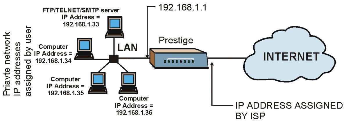
flowchart
graph TD
    A["Priavte network"] --> B["IP addresses assigned by user"]
    B --> C["Computer IP Address = 192.168.1.34"]
    B --> D["Computer IP Address = 192.168.1.35"]
    B --> E["Computer IP Address = 192.168.1.36"]
    C --> F["LAN"]
    D --> F
    E --> F
    F --> G["Prestige"]
    G --> H["INTERNET"]
    H --> I["IP ADDRESS ASSIGNED BY ISP"]
    G --> J["FTP/TELNET/SMTP server IP Address = 192.168.1.33"]
    G --> K["192.168.1.1"]
Figure 22-10 Multiple Servers Behind NAT Example
22.5 General NAT Examples
The following are some examples of NAT configuration.
22.5.1 Example 1: Internet Access Only
In the following Internet access example, you only need one rule where your ILAs (Inside Local addresses) all map to one dynamic IGA (Inside Global Address) assigned by your ISP.
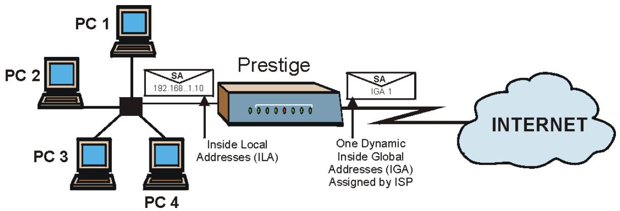
flowchart
graph LR
    PC1["PC 1"] -->|SA 192.168..1.10| Prestige["Prestige"]
    PC2["PC 2"] -->|SA 192.168..1.10| Prestige
    PC3["PC 3"] -->|SA 192.168..1.10| Prestige
    PC4["PC 4"] -->|SA 192.168..1.10| Prestige
    Prestige -->|Inside Local Addresses (ILA)| PC3
    Prestige -->|One Dynamic Inside Global Addresses (IGA) Assigned by ISP| SA["SA IGA 1"]
    SA --> Internet["INTERNET"]
Figure 22-11 NAT Example 1
Menu 4 - Internet Access Setup
ISP's Name= MyISP
Encapsulation= RFC 1483
Multiplexing= LLC-based
VPI #= 8
VCI #= 35
ATM QoS Type= UBR
Peak Cell Rate (PCR)= 0
Sustain Cell Rate (SCR)= 0
Maximum Burst Size (MBS)= 0
My Login= N/A
My Password= N/A
ENET ENCAP Gateway= N/A
IP Address Assignment= Static
IP Address= 0.0.0.0
Network Address Translation= SUA Only
Address Mapping Set= N/A
Press ENTER to Confirm or ESC to Cancel:
Figure 22-12 Menu 4 Internet Access & NAT Example
From menu 4, choose the SUA Only option from the Network Address Translation field. This is the Many-to-One mapping discussed in section 22.5. The SUA Only read-only option from the Network Address Translation field in menus 4 and 11.3 is specifically pre-configured to handle this case.
22.5.2 Example 2: Internet Access with an Inside Server
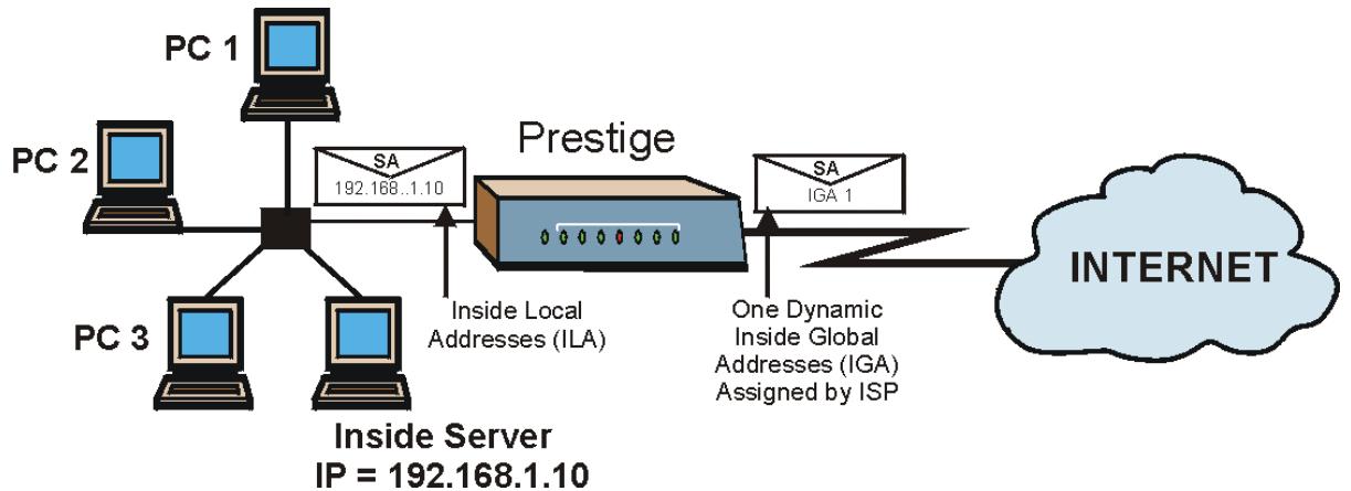
flowchart
graph TD
    PC1["PC 1"] -->|SA 192.168..1.10| Central["Central Node"]
    PC2["PC 2"] -->|SA 192.168..1.10| Central
    PC3["PC 3"] -->|SA 192.168..1.10| Central
    Central -->|Inside Local Addresses (ILA)| Prestige["Prestige"]
    Central -->|One Dynamic Inside Global Addresses (IGA) Assigned by ISP| Internet["INTERNET"]
    style Central fill:#f9f,stroke:#333
    style Internet fill:#ccf,stroke:#333
Figure 22-13 NAT Example 2
In this case, you do exactly as above (use the convenient pre-configured SUA Only set) and also go to menu 15.2 to specify the Inside Server behind the NAT as shown in the next figure.
| Rule | Start Port No. | End Port No. | IP Address |
| 1. | Default | Default | 192.168.1.10 |
| 2. | 0 | 0 | 0.0.0.0 |
| 3. | 0 | 0 | 0.0.0.0 |
| 4. | 0 | 0 | 0.0.0.0 |
| 5. | 0 | 0 | 0.0.0.0 |
| 6. | 0 | 0 | 0.0.0.0 |
| 7. | 0 | 0 | 0.0.0.0 |
| 8. | 0 | 0 | 0.0.0.0 |
| 9. | 0 | 0 | 0.0.0.0 |
| 10. | 0 | 0 | 0.0.0.0 |
| 11. | 0 | 0 | 0.0.0.0 |
| 12. | 0 | 0 | 0.0.0.0 |
Figure 22-14 Menu 15.2.1 Specifying an Inside Server
22.5.3 Example 3: Multiple Public IP Addresses With Inside Servers
In this example, there are 3 IGAs from our ISP. There are many departments but two have their own FTP server. All departments share the same router. The example will reserve one IGA for each department with an FTP server and all departments use the other IGA. Map the FTP servers to the first two IGAs and the other LAN traffic to the remaining IGA. Map the third IGA to an inside web server and mail server. Four rules need to be configured, two bi-directional and two uni-directional as follows.
Rule 1. Map the first IGA to the first inside FTP server for FTP traffic in both directions (1 : 1 mapping, giving both local and global IP addresses).
Rule 2. Map the second IGA to our second inside FTP server for FTP traffic in both directions (1 : 1 mapping, giving both local and global IP addresses).
Rule 3. Map the other outgoing LAN traffic to IGA3 (Many : 1 mapping).
Rule 4. You also map your third IGA to the web server and mail server on the LAN. Type Server allows you to specify multiple servers, of different types, to other computers behind NAT on the LAN.
The example situation looks somewhat like this:
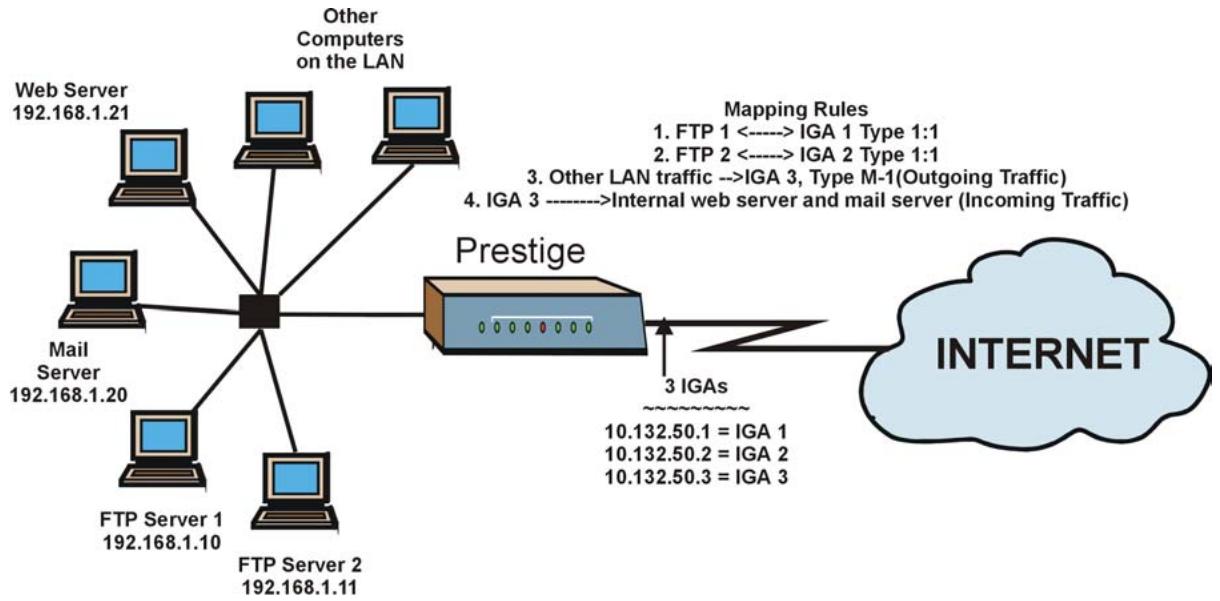
flowchart
graph TD
    A["Web Server 192.168.1.21"] --> B["Central Node"]
    C["Mail Server 192.168.1.20"] --> B
    D["FTP Server 1 192.168.1.10"] --> B
    E["FTP Server 2 192.168.1.11"] --> B
    F["Other Computers on the LAN"] --> B
    G["Prestige"] --> H["3 IGAs"]
    H --> I["INTERNET"]
    style I fill:#cce5ff,stroke:#333
    note right of B: Mapping Rules
    note left of B: 3. Other LAN traffic --> IGA1["IGA 1 Type 1:1"]
    note right of B: 4. IGA3["IGA 3"] --> IGA2["IGA 2 Type 1:1"]
    note right of B: 3. Other LAN traffic --> IGA3["IGA 3, Type M-1(Outgoing Traffic)"]
    note right of B: Internal web server and mail server (Incoming Traffic)
Figure 22-15 NAT Example 3
Step 1. In this case you need to configure Address Mapping Set 1 from Menu 15.1 - Address Mapping Sets. Therefore you must choose the Full Feature option from the Network Address Translation field (in menu 4 or menu 11.3) in Figure 22-16.
Step 2. Then enter 15 from the main menu.
Step 3. Enter 1 to configure the Address Mapping Sets.
Step 4. Enter 1 to begin configuring this new set. Enter a Set Name, choose the Edit Action and then enter 1 for the Select Rule field. Press [ENTER] to confirm.
Step 5. Select Type as One-to-One (direct mapping for packets going both ways), and enter the local Start IP as 192.168.1.10 (the IP address of FTP Server 1), the global Start IP as 10.132.50.1 (our first IGA). (See Figure 22-17).
Step 6. Repeat the previous step for rules 2 to 4 as outlined above.
Step 7. When finished, menu 15.1.1 should look like as shown in.
Menu 11.3 - Remote Node Network Layer Options
IP Options: Bridge Options:
IP Address Assignment= Static Ethernet Addr Timeout (min)= 0
Rem IP Addr: 0.0.0.0
Rem Subnet Mask= 0.0.0.0
My WAN Addr= 0.0.0.0
NAT= Full Feature
Address Mapping Set= 2
Metric= 2
Private= No
RIP Direction= Both
Version= RIP-2B
Multicast= IGMP-v2
IP Policies=
Press ENTER to Confirm or ESC to Cancel:
Figure 22-16 Example 3: Menu 11.3
The following figures show how to configure the first rule
Menu 15.1.1.1 Address Mapping Rule
Type= One-to-One
Local IP:
    Start= 192.168.1.10
    End = N/A
Global IP:
    Start= 10.132.50.1
    End = N/A
Server Mapping Set= N/A
Press ENTER to Confirm or ESC to Cancel:
Press Space Bar to Toggle.
Figure 22-17 Example 3: Menu 15.1.1.1
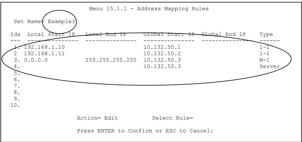
text_image
Menu 15.1.1 - Address Mapping Rules Set Name= Example3 Idx Local Start IP Local End IP Global Start IP Global End IP Type 1. 192.168.1.10 10.132.50.1 1-1 2 192.168.1.11 10.132.50.2 1-1 3. 0.0.0.0 255.255.255.255 10.132.50.3 M-1 4. 10.132.50.3 Server 5. 6. 7. 8. 9. 10. Action= Edit Select Rule= Press ENTER to Confirm or ESC to Cancel:Figure 22-18 Example 3: Final Menu 15.1.1
Now configure the IGA3 to map to our web server and mail server on the LAN.
Step 8. Enter 15 from the main menu.
Step 9. Enter 2 in Menu 15 - NAT Setup.
Step 10. Enter 1 in Menu 15.2 - NAT Server Sets to see the following menu. Configure it as shown.
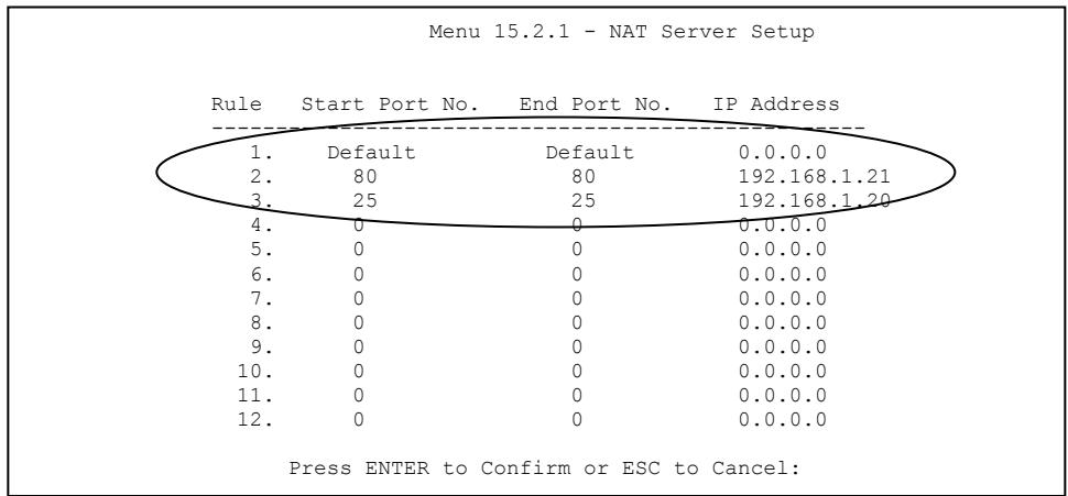
other
Menu 15.2.1 - NAT Server Setup | Rule | Start Port No. | End Port No. | IP Address | |---|---|---|---| | 1. | Default | Default | 0.0.0.0 | | 2. | 80 | 80 | 192.168.1.21 | | 3. | 25 | 25 | 192.168.1.20 | | 4. | 0 | 0 | 0.0.0.0 | | 5. | 0 | 0 | 0.0.0.0 | | 6. | 0 | 0 | 0.0.0.0 | | 7. | 0 | 0 | 0.0.0.0 | | 8. | 0 | 0 | 0.0.0.0 | | 9. | 0 | 0 | 0.0.0.0 | | 10. | 0 | 0 | 0.0.0.0 | | 11. | 0 | 0 | 0.0.0.0 | | 12. | 0 | 0 | 0.0.0.0 | Press ENTER to Confirm or ESC to Cancel:Example 3: Menu 15.2.1
22.5.4 Example 4: NAT Unfriendly Application Programs
Some applications do not support NAT Mapping using TCP or UDP port address translation. In this case it is better to use Many-to-Many No Overload mapping as port numbers do not change for Many-to-Many No Overload (and One-to-One) NAT mapping types. The following figure illustrates this.
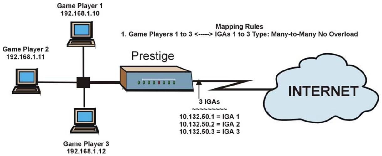
flowchart
graph LR
    A["Game Player 1\n192.168.1.10"] --> B["Computer"]
    C["Game Player 2\n192.168.1.11"] --> B
    D["Game Player 3\n192.168.1.12"] --> B
    B --> E["Prestige"]
    E --> F["3 IGAs\n10.132.50.1 = IGA 1\n10.132.50.2 = IGA 2\n10.132.50.3 = IGA 3"]
    G["INTERNET"] --> E
    style G fill:#cce5ff,stroke:#333
Figure 22-19 NAT Example 4
Other applications such as some gaming programs are NAT unfriendly because they embed addressing information in the data stream. These applications won't work through NAT even when using One-to-One and Many-to-Many No Overload mapping types.
Follow the steps outlined in example 3 to configure these two menus as follows.
Menu 15.1.1.1 Address Mapping Rule
Type= Many-to-Many No Overload
Local IP:
    Start= 192.168.1.10
    End = 192.168.1.12
Global IP:
    Start= 10.132.50.1
    End = 10.132.50.3
Server Mapping Set= N/A
Press ENTER to Confirm or ESC to Cancel:
Figure 22-20 Example 4: Menu 15.1.1.1 Address Mapping Rule
After you've configured your rule, you should be able to check the settings in menu 15.1.1 as shown next.
Menu 15.1.1 - Address Mapping Rules
Set Name= Example4
Idx Local Start IP Local End IP Global Start IP Global End IP Type
1. 192.168.1.10 192.168.1.12 10.132.50.1 10.132.50.3 M:M NO OV
2.
3.
4.
5.
6.
7.
8.
9.
10.
Action= Edit Select Rule=
Press ENTER to Confirm or ESC to Cancel:
Figure 22-21 Example 4: Menu 15.1.1 Address Mapping Rules
Part VIII:
SMT Advanced Management
This part discusses filtering setup, SNMP, system security, system information and diagnosis, firmware and configuration file maintenance, system maintenance, remote management, IP policy routing and call scheduling.
See the web configurator parts of this guide for background information on features configurable by web configurator and SMT.
Chapter 23
Filter Configuration
This chapter shows you how to create and apply filters.
23.1 About Filtering
Your Prestige uses filters to decide whether or not to allow passage of a data packet and/or to make a call. There are two types of filter applications: data filtering and call filtering. Filters are subdivided into device and protocol filters, which are discussed later.
Data filtering screens data to determine if the packet should be allowed to pass. Data filters are divided into incoming and outgoing filters, depending on the direction of the packet relative to a port. Data filtering can be applied on either the WAN side or the Ethernet side. Call filtering is used to determine if a packet should be allowed to trigger a call.
Outgoing packets must undergo data filtering before they encounter call filtering. Call filters are divided into two groups, the built-in call filters and user-defined call filters. Your Prestige has built-in call filters that prevent administrative, for example, RIP packets from triggering calls. These filters are always enabled and not accessible to you. Your Prestige applies the built-in filters first and then the user-defined call filters, if applicable, as shown next.
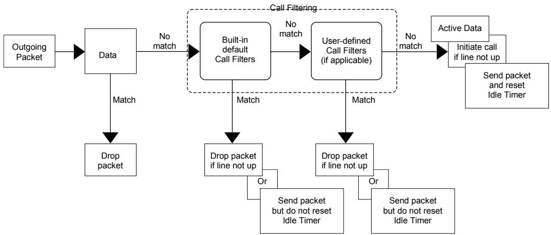
flowchart
graph TD
    A["Outgoing Packet"] --> B["Data"]
    B -->|Match| C["Drop packet"]
    B -->|No match| D["Built-in default Call Filters"]
    D -->|Match| E["Drop packet if line not up"]
    D -->|No match| F["User-defined Call Filters (if applicable)"]
    F -->|Match| G["Drop packet if line not up"]
    F -->|No match| H["Active Data"]
    H --> I["Initiate call if line not up"]
    I --> J["Send packet and reset Idle Timer"]
    D --> K["Send packet but do not reset Idle Timer"]
    F --> L["Send packet but do not reset Idle Timer"]
    style D fill:#f9f,stroke:#333
    style F fill:#f9f,stroke:#333
    style H fill:#ccf,stroke:#333
Figure 23-1 Outgoing Packet Filtering Process
Two sets of factory filter rules have been configured in menu 21 to prevent NetBIOS traffic from triggering calls. A summary of their filter rules is shown in the figures that follow.
The following figure illustrates the logic flow when executing a filter rule.
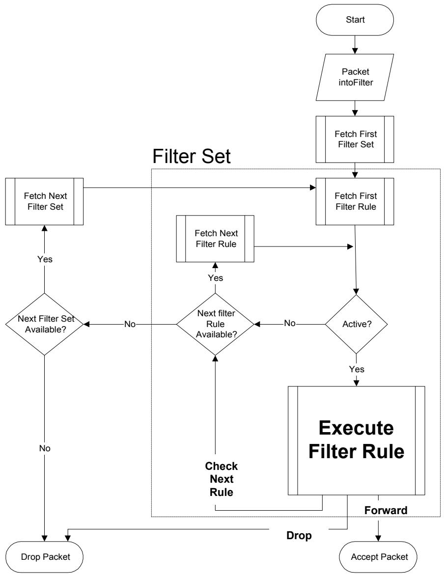
flowchart
graph TD
    A["Start"] --> B["Packet intoFilter"]
    B --> C["Fetch First Filter Set"]
    C --> D["Fetch First Filter Rule"]
    D --> E{Active?}
    E -->|Yes| F["Execute Filter Rule"]
    E -->|No| G{Next filter Rule Available?}
    G -->|Yes| H["Fetch Next Filter Set"]
    H --> I{Next Filter Set Available?}
    I -->|No| J["Drop Packet"]
    I -->|Yes| K["Check Next Rule"]
    K --> L["Receive"]
    L --> M["Accept Packet"]
    M --> N["Forward"]
    N --> O["Drop"]
    style A fill:#f9f,stroke:#333
    style B fill:#ccf,stroke:#333
    style C fill:#cfc,stroke:#333
    style D fill:#fcc,stroke:#333
    style E fill:#cff,stroke:#333
    style F fill:#ffc,stroke:#333
    style G fill:#cfc,stroke:#333
    style H fill:#fcc,stroke:#333
    style I fill:#ffc,stroke:#333
    style J fill:#fcc,stroke:#333
    style K fill:#ffc,stroke:#333
    style L fill:#fcc,stroke:#333
    style M fill:#ffc,stroke:#333
    style N fill:#fcc,stroke:#333
Figure 23-2 Filter Rule Process
You can apply up to four filter sets to a particular port to block various types of packets. Because each filter set can have up to six rules, you can have a maximum of 24 rules active for a single port.
For incoming packets, your Prestige applies data filters only. Packets are processed depending on whether a match is found. The following sections describe how to configure filter sets.
The Filter Structure of the Prestige
A filter set consists of one or more filter rules. Usually, you would group related rules, for example, all the rules for NetBIOS, into a single set and give it a descriptive name. You can configure up to twelve filter sets with six rules in each set, for a total of 72 filter rules in the system.
23.2 Configuring a Filter Set for the Prestige 650H and the Prestige 650HW
To configure a filter set, follow the steps shown next.
Step 1. Enter 21 in the main menu to display Menu 21 – Filter Set Configuration.
| Menu 21 - Filter Set Configuration | |||
| Filter Set # | Comments | Filter Set # | Comments |
| 1 | 7 | ||
| 2 | NetBIOS_WAN | 8 | |
| 3 | NetBIOS_LAN | 9 | |
| 4 | IGMP | 10 | |
| 5 | 11 | WebSet1 | |
| 6 | 12 | WebSet2 | |
| Enter Filter Set Number to Configure= 0 | |||
| Edit Comments= N/A | |||
| Press ENTER to Confirm or ESC to Cancel: | |||
Figure 23-3 Menu 21 Filter Set Configuration (P650H/HW)
Step 2. Type the filter set to configure (no. 1 to 12) and press [ENTER].
Step 3. Type a descriptive name or comment in the Edit Comments field and press [ENTER].
Step 4. Press [ENTER] at the message “Press ENTER to confirm…” to display Menu 21.2 – Filter Rules Summary (that is, if you selected filter set 2 in menu 21).
| Menu 21.2 - Filter Rules Summary | |||
| # A Type | Filter Rules | M m n | |
| 1 Y IP | Pr=6, SA=0.0.0.0, DA=0.0.0.0, DP=137 | N D N | |
| 2 Y IP | Pr=6, SA=0.0.0.0, DA=0.0.0.0, DP=138 | N D N | |
| 3 Y IP | Pr=6, SA=0.0.0.0, DA=0.0.0.0, DP=139 | N D N | |
| 4 Y IP | Pr=17, SA=0.0.0.0, DA=0.0.0.0, DP=137 | N D N | |
| 5 Y IP | Pr=17, SA=0.0.0.0, DA=0.0.0.0, DP=138 | N D N | |
| 6 Y IP | Pr=17, SA=0.0.0.0, DA=0.0.0.0, DP=139 | N D F | |
| Enter Filter Rule Number (1-6) to Configure: | |||
Figure 23-4 NetBIOS_WAN Filter Rules Summary
| Menu 21.3 - Filter Rules Summary | |||
| # A Type | Filter Rules | M m n | |
| - - - - - - - - - - - - - - - - - - - - - - - - - - - - - - - - - - - - - - - - - - - - - - - - - - - - - - - - - - - - - - - - - - - - - - - - - - - - - - - - - - - - - - - - - | |||
| 1 Y IP | Pr=17, SA=0.0.0.0, SP=137, DA=0.0.0.0, DP=53 | N D F | |
| 2 N | |||
| 3 N | |||
| 4 N | |||
| 5 N | |||
| 6 N | |||
| Enter Filter Rule Number (1-6) to Configure: | |||
Figure 23-5 NetBIOS_LAN Filter Rules Summary
| Menu 21.4 - Filter Rules Summary | |||
| # A Type | Filter Rules | M m n | |
| - - | ---- | - - - | |
| 1 Y Gen | Off=0, Len=3, Mask=ffffff, Value=01005e | N D F | |
| 2 N | |||
| 3 N | |||
| 4 N | |||
| 5 N | |||
| 6 N | |||
| Enter Filter Rule Number (1-6) to Configure: | |||
Figure 23-6 IGMP Filter Rules Summary
23.3 Configuring a Filter Set for the Prestige 650R and the Prestige 650R-E
To configure a filter set, follow the steps shown next.
Step 1. Enter 21 in the main menu to display Menu 21 – Filter Set Configuration.
| Menu 21 - Filter Set Configuration | |||
| Filter Set # | Comments | Filter Set # | Comments |
| 1 | NetBIOS_WAN | 7 | _ |
| 2 | NetBIOS_LAN | 8 | _ |
| 3 | TELNET_WAN | 9 | _ |
| 4 | PPPoE | 10 | _ |
| 5 | FTP_WAN | 11 | WebSet1 |
| 6 | _ | 12 | WebSet2 |
| Enter Filter Set Number to Configure= 0 | |||
| Edit Comments= N/A | |||
| Press ENTER to Confirm or ESC to Cancel: | |||
Figure 23-7 Menu 21 Filter Set Configuration (P650R and P650R-E)
Step 2. Type the filter set to configure (no. 1 to 12) and press [ENTER].
Step 3. Type a descriptive name or comment in the Edit Comments field and press [ENTER].
Step 4. Press [ENTER] at the message “Press ENTER to confirm…” to display Menu 21.4 – Filter Rules Summary (that is, if you selected filter set 4 in menu 21).
See Figure 23-4 for the summary of the NetBIOS WAN rules and Figure 23-5 for the summary of the NetBIOS LAN rules.
| Menu 21.3 - Filter Rules Summary | |||
| # A Type | Filter Rules | M m n | |
| - - - - - - - - - - - - - - - - - - - - - - - - - - - - - - - - - - - - - - - - - - - - - - - - - - - - - - - - - - - - - - - - - - - - - - - - - - - - - - - - - - - - - - - - - - - - - | |||
| 1 Y IP | Pr=6, SA=0.0.0.0, DA=0.0.0.0, DP=23 | N D F | |
| 2 N | |||
| 3 N | |||
| 4 N | |||
| 5 N | |||
| 6 N | |||
| Enter Filter Rule Number (1-6) to Configure: | |||
Figure 23-8 TELNET_WAN Filter Rules Summary
| Menu 21.4 - Filter Rules Summary | |||
| # A Type | Filter Rules | M m n | |
| - - - - - - - - - - - - - - - - - - - - - - - - - - - - - - - - - - - - - - - - - - - - - - - - - - - - - - - - - - - - - - - - - - - - - - - - - - - - - - - - - - - - - - - - - - - - - - - - - - - - - | |||
| 1 Y Gen | Off=12, Len=2, Mask=ffff, Value=8863 | N F N | |
| 2 Y Gen | Off=12, Len=2, Mask=ffff, Value=8864 | N F D | |
| 3 N | |||
| 4 N | |||
| 5 N | |||
| 6 N | |||
| Enter Filter Rule Number (1-6) to Configure: | |||
Figure 23-9 PPPoE Filter Rules Summary
| Menu 21.5 - Filter Rules Summary | ||
| # A Type | Filter Rules | M m n |
| - - | ---- | - - - |
| 1 N | ||
| 2 N | ||
| 3 N | ||
| 4 N | ||
| 5 N | ||
| 6 N | ||
| Enter Filter Rule Number (1-6) to Configure: | ||
Figure 23-10 FTP_WAN Filter Rules Summary
23.3.1 Filter Rules Summary Menus
The following tables briefly describe the abbreviations used in menu 21.x.
Table 23-1 Abbreviations Used in the Filter Rules Summary Menu
| FIELD | DESCRIPTION |
| # | The filter rule number: 1 to 6. |
| A | Active: “Y” means the rule is active. “N” means the rule is inactive. |
| Type | The type of filter rule: “GEN” for Generic, “IP” for TCP/IP. |
| Filter Rules | These parameters are displayed here. |
| M | More.“Y” means there are more rules to check which form a rule chain with the present rule.An action cannot be taken until the rule chain is complete.“N” means there are no more rules to check. You can specify an action to be taken for instance, forward the packet, drop the packet or check the next rule. For the latter, the next rule is independent of the rule just checked. |
| m | Action Matched.“F” means to forward the packet immediately and skip checking the remaining rules.“D” means to drop the packet.“N” means to check the next rule. |
| n | Action Not Matched.“F” means to forward the packet immediately and skip checking the remaining rules.“D” means to drop the packet.“N” means to check the next rule. |
The protocol dependent filter rules abbreviation are listed as follows:
Table 23-2 Rule Abbreviations Used
| FILTER TYPE | DESCRIPTION |
| IP | |
| Pr | Protocol |
| SA | Source Address |
| SP | Source Port Number |
| DA | Destination Address |
| DP | Destination Port Number |
| GEN |
Table 23-2 Rule Abbreviations Used
| FILTER TYPE | DESCRIPTION |
| Off | Offset |
| Len | Length |
23.4 Configuring a Filter Rule
To configure a filter rule, type its number in Menu 21.x – Filter Rules Summary and press [ENTER] to open menu 21.x.1 for the rule.
There are two types of filter rules: TCP/IP and Generic. Depending on the type of rule, the parameters for each type will be different. Use [SPACE BAR] to select the type of rule that you want to create in the Filter Type field and press [ENTER] to open the respective menu.
To speed up filtering, all rules in a filter set must be of the same class, for instance, protocol filters or generic filters. The class of a filter set is determined by the first rule that you create. When applying the filter sets to a port, separate menu fields are provided for protocol and device filter sets. If you include a protocol filter set in a device filters field or vice versa, the Prestige will warn you and will not allow you to save.
23.4.1 TCP/IP Filter Rule
This section shows you how to configure a TCP/IP filter rule. TCP/IP rules allow you to base the rule on the fields in the IP and the upper layer protocol, for example, UDP and TCP headers.
To configure TCP/IP rules, select TCP/IP Filter Rule from the Filter Type field and press [ENTER] to open Menu 21.x.1 – TCP/IP Filter Rule, as shown next.
| Menu 21.1.1 - TCP/IP Filter Rule |
| Filter #: 1,1 Filter Type= TCP/IP Filter Rule Active= No IP Protocol= 0 IP Source Route= No Destination: IP Addr= IP Mask= Port #= Port # Comp= None Source: IP Addr= IP Mask= Port #= Port # Comp= None TCP Estab= N/A More= No Log= None Action Matched= Check Next Rule Action Not Matched= Check Next Rule |
| Press ENTER to Confirm or ESC to Cancel: Press Space Bar to Toggle. |
Figure 23-11 Menu 21.x.1 TCP/IP Filter Rule
The following table describes how to configure your TCP/IP filter rule.
Table 23-3 Menu 21.x.1 TCP/IP Filter Rule
| FIELD | DESCRIPTION | EXAMPLE |
| Filter # | This is the filter set, filter rule coordinates, for instance, 2, 3 refers to the second filter set and the third filter rule of that set. | 1,1 |
| Filter Type | Use [SPACE BAR] and then [ENTER] to choose a rule. Parameters displayed for each type will be different.Choices are TCP/IP Filter Rule or Generic Filter Rule. | TCP/IP Filter Rule |
| Active | Select Yes to activate or No to deactivate the filter rule. | No (default) |
| IP Protocol | This is the upper layer protocol, for example, TCP is 6, UDP is 17 and ICMP is 1. The value must be between 0 and 255. A value of O matches ANY protocol. | 0 to 255 |
| IP Source Route | IP Source Route is an optional header that dictates the route an IP packet takes from its source to its destination. If Yes, the rule applies to any packet with an IP source route. The majority of IP packets do not have source route. | No (default) |
| Destination:IP Addr | Type the destination IP address of the packet you want to filter. This field is ignored if it is 0.0.0.0. | IP address |
Table 23-3 Menu 21.x.1 TCP/IP Filter Rule
| FIELD | DESCRIPTION | EXAMPLE |
| IP Mask | Type the IP mask to apply to the Destination: IP Addr field. | IP mask |
| Port # | Type the destination port of the packets you want to filter. The field range is 0 to 65535. A 0 field is ignored. | 0 to 65535 |
| Port # Comp | Select the comparison to apply to the destination port in the packet against the value given inDestination: Port #. Choices are None, Less, Greater, Equal or Not Equal. | None |
| Source:IP Addr | Type the source IP Address of the packet you want to filter. A 0.0.0.0 field is ignored. | IP address |
| IP Mask | Type the IP mask to apply to theSource: IP Addr field. | IP mask |
| Port # | Type the source port of the packets you want to filter. The range of this field is 0 to 65535. A 0 field is ignored. | 0 to 65535 |
| Port # Comp | Select the comparison to apply to the source port in the packet against the value given inSource: Port # field.Choices are None, Less, Greater, Equal or Not Equal. | None |
| TCP Estab | This applies only when the IP Protocol field is 6, TCP. IfYes, the rule matches packets that want to establish TCP connection(s) (SYN=1 and ACK=0); else it is ignored. | No(default) |
| More | If Yes, a matching packet is passed to the next filter rule before an action is taken or else the packet is disposed of according to the action fields.If More is Yes, then Action Matched and Action Not Matched will be N/A. | No(default) |
| Log | Select the logging option from the following:None – No packets will be logged.Action Matched – Only packets that match the rule parameters will be logged.Action Not Matched – Only packets that do not match the rule parameters will be logged.Both – All packets will be logged. | None |
| Action Matched | Select the action for a matching packet. Choices are Check Next Rule, Forward or Drop. | Check Next Rule(default) |
Table 23-3 Menu 21.x.1 TCP/IP Filter Rule
| FIELD | DESCRIPTION | EXAMPLE |
| Action Not Matched | Select the action for a packet not matching the rule.Choices are Check Next Rule, Forward or Drop. | Check Next Rule (default) |
| When you have completed this menu, press [ENTER] at the prompt “Press ENTER to confirm or ESC to cancel” to save your configuration or press [ESC] to cancel and go back to the previous screen. | ||
The following figure illustrates the logic flow of an IP filter.
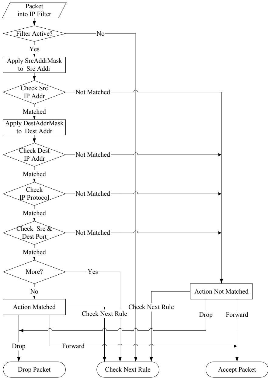
flowchart
graph TD
    A["Packet into IP Filter"] --> B{Filter Active?}
    B -->|Yes| C["Apply SrcAddrMask to Src Addr"]
    C --> D{Check Src IP Addr}
    D -->|Matched| E["Apply DestAddrMask to Dest Addr"]
    E --> F{Check Dest IP Addr}
    F -->|Matched| G{Check IP Protocol}
    G -->|Matched| H{Check Src & Dest Port}
    H -->|Matched| I{More?}
    I -->|No| J["Action Matched"]
    I -->|Yes| K["Action Not Matched"]
    J --> L["Drop Packet"]
    J --> M["Check Next Rule"]
    J --> N["Accept Packet"]
    K --> O["Check Next Rule"]
    L --> P["Forward"]
    M --> Q["Forward"]
    N --> R["Drop"]
    N --> S["Accept Packet"]
    style A fill:#f9f,stroke:#333
    style K fill:#f9f,stroke:#333
    style L fill:#ccf,stroke:#333
    style M fill:#ccf,stroke:#333
    style N fill:#ccf,stroke:#333
Figure 23-12 Executing an IP Filter
23.4.2 Generic Filter Rule
This section shows you how to configure a generic filter rule. The purpose of generic rules is to allow you to filter non-IP packets. For IP, it is generally easier to use the IP rules directly.
For generic rules, the Prestige treats a packet as a byte stream as opposed to an IP packet. You specify the portion of the packet to check with the Offset (from 0) and the Length fields, both in bytes. The Prestige applies the Mask (bit-wise ANDing) to the data portion before comparing the result against the Value to determine a match. The Mask and Value fields are specified in hexadecimal numbers. Note that it takes two hexadecimal digits to represent a byte, so if the length is 4, the value in either field will take 8 digits, for example, FFFFFFFF.
To configure a generic rule select an empty filter set in menu 21, for example 6. Select Generic Filter Rule in the Filter Type field and press [ENTER] to open Menu 21.6.1 – Generic Filter Rule, as shown in the following figure.
Menu 21.6.1 - Generic Filter Rule
Filter #: 6,1
Filter Type= Generic Filter Rule
Active= No
Offset= 0
Length= 0
Mask= N/A
Value= N/A
More= No Log= None
Action Matched= Check Next Rule
Action Not Matched= Check Next Rule

Press ENTER to Confirm or ESC to Cancel:
Press Space Bar to Toggle.
Figure 23-13 Menu 21.6.1 Generic Filter Rule
The next table describes the fields in the Generic Filter Rule menu.
Table 23-4 Menu 21.6.1 Generic Filter Rule
| FIELD | DESCRIPTION | EXAMPLE |
| Filter # | This is the filter set, filter rule coordinates, for instance, 2, 3 refers to the second filter set and the third rule of that set. | 6,1 |
| Filter Type | Press [SPACE BAR] and then [ENTER] to select a type of rule.Parameters displayed below each type will be different. Choices are Generic Filter Rule or TCP/IP Filter Rule. | Generic Filter Rule |
| Active | Select Yes to turn on or No to turn off the filter rule. | No (default) |
| Offset | Type the starting byte of the data portion in the packet that you want to compare. The range for this field is from 0 to 255. | 0 (default) |
| Length | Type the byte count of the data portion in the packet that you want to compare. The range for this field is 0 to 8. | 0 (default) |
| Mask | Type the mask (in Hexadecimal) to apply to the data portion before comparison. | |
| Value | Type the value (in Hexadecimal) to compare with the data portion. | |
| More | If Yes, a matching packet is passed to the next filter rule before an action is taken or else the packet is disposed of according to the action fields.If More is Yes, then Action Matched and Action Not Matched will be N/A. | No (default) |
| Log | Select the logging option from the following:None – No packets will be logged.Action Matched – Only matching packets and rules will be logged.Action Not Matched – Only packets that do not match the rule parameters will be logged.Both – All packets will be logged. | None |
| Action Matched | Select the action for a matching packet. Choices are Check Next Rule, Forward or Drop. | Check Next Rule (default) |
| Action Not Matched | Select the action for a packet not matching the rule. Choices are Check Next Rule, Forward or Drop. | Check Next Rule (default) |
| When you have completed this menu, press [ENTER] at the prompt “Press ENTER to confirm or ESC to cancel” to save your configuration or press [ESC] to cancel and go back to the previous screen. | ||
23.5 Filter Types and NAT
There are two classes of filter rules, Generic Filter Device rules and Protocol Filter (TCP/IP) rules. Generic Filter rules act on the raw data from/to LAN and WAN. Protocol Filter rules act on IP packets.
When NAT (Network Address Translation) is enabled, the inside IP address and port number are replaced on a connection-by-connection basis, which makes it impossible to know the exact address and port on the wire. Therefore, the Prestige applies the protocol filters to the “native” IP address and port number before NAT for outgoing packets and after NAT for incoming packets. On the other hand, the generic (or device) filters are applied to the raw packets that appear on the wire. They are applied at the point where the Prestige is receiving and sending the packets; for instance, the interface. The interface can be an Ethernet, or any other hardware port. The following figure illustrates this.
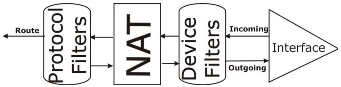
flowchart
graph LR
    A["Protocol Filters"] --> B["NAT"]
    B --> C["Device Filters"]
    C --> D["Interface"]
    A <-->|Route| A
    B <-->|Incoming| C
    C <-->|Outgoing| D
Figure 23-14 Protocol and Device Filter Sets
23.6 Example Filter
Let's look at an example to block outside users from telnetting into the Prestige.
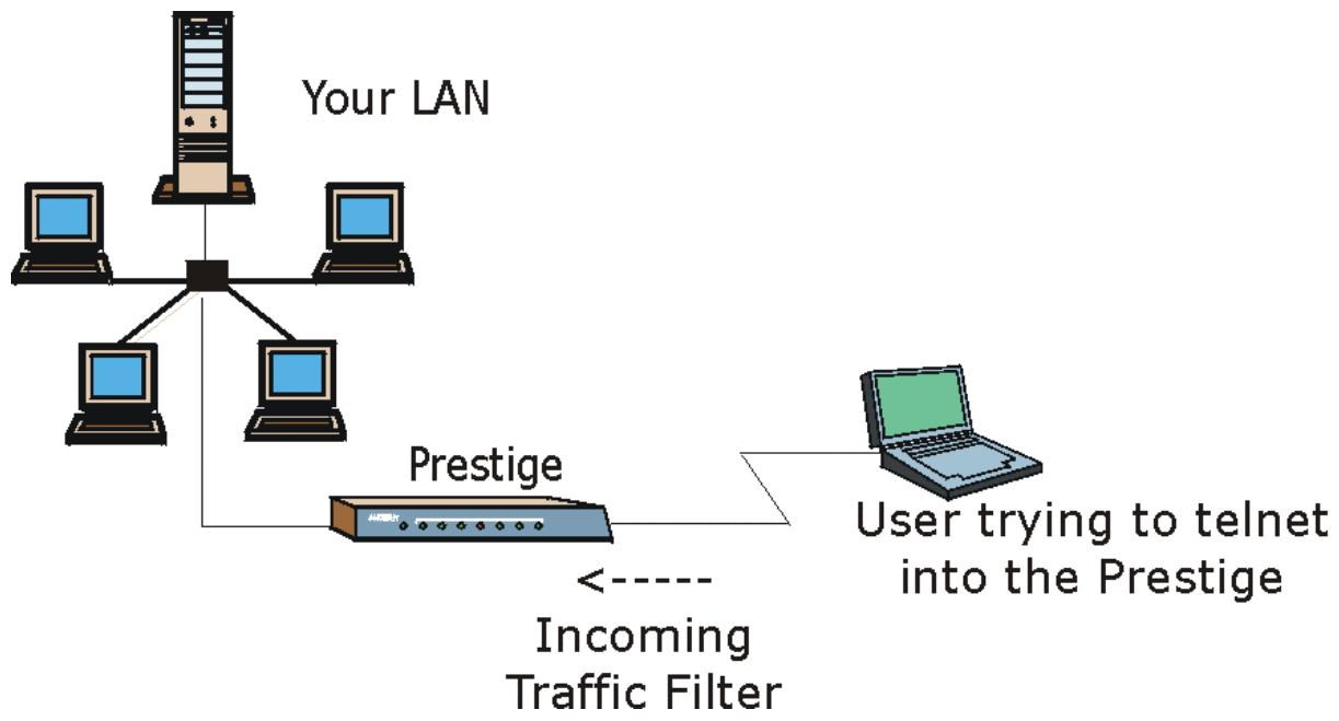
flowchart
graph TD
    A["User"] --> B["Your LAN"]
    B --> C["Central Network"]
    C --> D["Prestige"]
    D --> E["Incoming Traffic Filter"]
    E --> F["User trying to telnet into the Prestige"]
Figure 23-15 Sample Telnet Filter
Step 1. Enter 21 in the main menu to display Menu 21 — Filter Set Configuration.
Step 2. Enter the index number of the filter set you want to configure (in this case 6).
Step 3. Type a descriptive name or comment in the Edit Comments field (for example, TELNET_WAN) and press [ENTER].
Step 4. Press [ENTER] at the message “Press [ENTER] to confirm or [ESC] to cancel” to open Menu 21.6 — Filter Rules Summary.
Step 5. Type 1 to configure the first filter rule. Make the entries in this menu as shown next.
When you press [ENTER] to confirm, the following screen appears. Note that there is only one filter rule in this set.
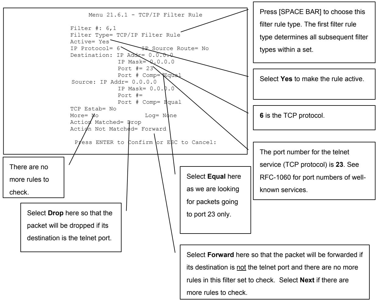
text_image
Menu 21.6.1 - TCP/IP Filter Rule Filter #: 6,1 Filter Type= TCP/IP Filter Rule Active= Yes IP Protocol= 6 IP Source Route= No Destination: IP Addr= 0.0.0.0 IP Mask= 0.0.0.0 Port # = 23 Port # Comp= Equal Source: IP Addr= 0.0.0.0 IP Mask= 0.0.0.0 Port # Port # Comp= Equal TCP Estab= No More= No Log= None Action Matched= Drop Action Not Matched= Forward Press ENTER to Confirm or ESC to Cancel: There are no more rules to check. Select Drop here so that the packet will be dropped if its destination is the telnet port. Press ENTER to Confirm or ESC to Cancel: Press [SPACE BAR] to choose this filter rule type. The first filter rule type determines all subsequent filter types within a set. Select Yes to make the rule active. 6 is the TCP protocol. Select Equal here as we are looking for packets going to port 23 only. The port number for the telnet service (TCP protocol) is 23. See RFC-1060 for port numbers of well- known services. Select Forward here so that the packet will be forwarded if its destination is not the telnet port and there are no more rules in this filter set to check. Select Next if there are more rules to check.Figure 23-16 Menu 21.6.1 Sample Filter
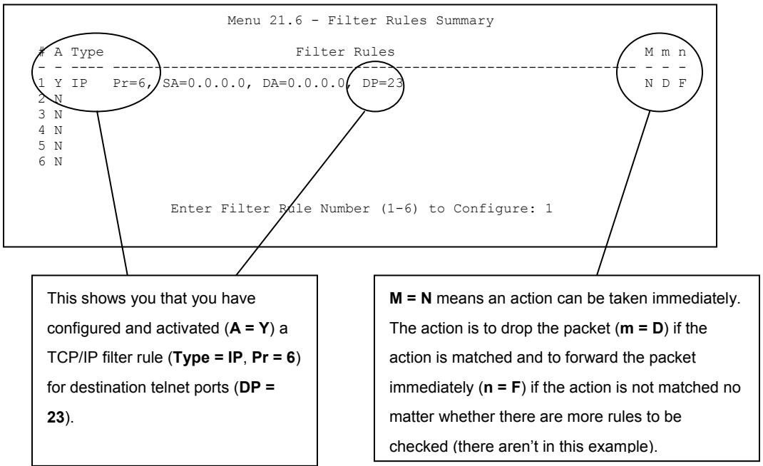
text_image
Menu 21.6 - Filter Rules SummaryA Type
Filter Rules 1 Y IP Pr=6, SA=0.0.0.0, DA=0.0.0.0, DP=23 2 N 3 N 4 N 5 N 6 N Enter Filter Rule Number (1-6) to Configure: 1 M m n N D F This shows you that you have configured and activated (A = Y) a TCP/IP filter rule (Type = IP, Pr = 6) for destination telnet ports (DP = 23). M = N means an action can be taken immediately. The action is to drop the packet (m = D) if the action is matched and to forward the packet immediately (n = F) if the action is not matched no matter whether there are more rules to be checked (there aren't in this example).Figure 23-17 Menu 21.6 Sample Filter Rules Summary
After you have created the filter set, you must apply it.
Step 1. Enter 11 in the main menu to display menu 11 and type the remote node number to edit.
Step 2. Go to the Edit Filter Sets field, press [SPACE BAR] to choose Yes and press [ENTER].
Step 3. This brings you to menu 11.5. Apply the example filter set (for example, filter set 3) in this menu as shown in the next section.
23.7 Applying Filters and Factory Defaults
This section shows you where to apply the filter(s) after you design it (them). Sets of factory default filter rules have been configured in menu 21 (but have not been applied) to filter traffic.
Table 23-5 Filter Sets Table
| FILTER SETS | DESCRIPTION |
| Input Filter Sets: | Apply filters for incoming traffic. You may apply protocol or device filter rules. See earlier in this chapter for information on filters. |
| Output Filter Sets: | Apply filters for traffic leaving the Prestige. You may apply filter rules for protocol or device filters. See earlier in this section for information on types of filters. |
| Call Filter Sets: | Apply filters to decide if a packet should be allowed to trigger a call. |
23.7.1 Ethernet Traffic
You seldom need to filter Ethernet traffic; however, the filter sets may be useful to block certain packets, reduce traffic and prevent security breaches. Go to menu 3.1 (shown next) and type the number(s) of the filter set(s) that you want to apply as appropriate. You can choose up to four filter sets (from twelve) by typing their numbers separated by commas, for example, 2, 4, 6, 11. The factory default filter set, NetBIOS_LAN, is inserted in the protocol filters field under Input Filter Sets in menu 3.1 in order to prevent local NetBIOS messages from triggering calls to the DNS server.
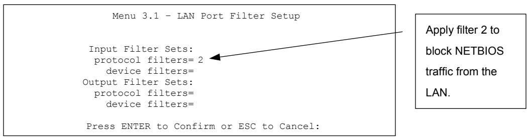
text_image
Menu 3.1 - LAN Port Filter Setup Input Filter Sets: protocol filters= 2 device filters= Output Filter Sets: protocol filters= device filters= Press ENTER to Confirm or ESC to Cancel: Apply filter 2 to block NETBIOS traffic from the LAN.Figure 23-18 Filtering Ethernet Traffic
23.7.2 Remote Node Filters
Go to menu 11.5 (shown next) and type the number(s) of the filter set(s) as appropriate. You can cascade up to four filter sets by typing their numbers separated by commas. The factory default filter set,
NetBIOS_WAN, is inserted in the protocol filters field under Call Filter Sets in menu 11.5 to block local NetBIOS traffic from triggering calls to the ISP.
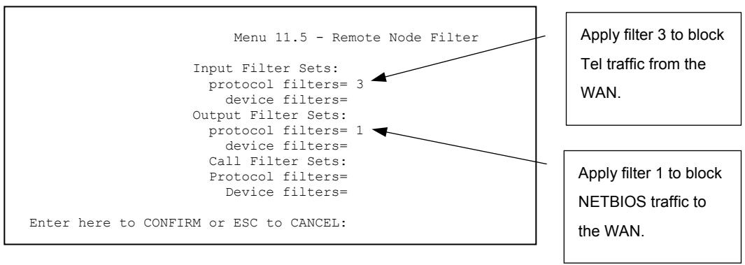
text_image
Menu 11.5 - Remote Node Filter Input Filter Sets: protocol filters= 3 device filters= Output Filter Sets: protocol filters= 1 device filters= Call Filter Sets: Protocol filters= Device filters= Enter here to CONFIRM or ESC to CANCEL: Apply filter 3 to block Tel traffic from the WAN. Apply filter 1 to block NETBIOS traffic to the WAN.Figure 23-19 Filtering Remote Node Traffic
Note that call filter sets are visible when you select PPPoA or PPPoE encapsulation.
Chapter 24
SNMP Configuration
This chapter explains SNMP Configuration menu 22.
24.1 SNMP Overview
Simple Network Management Protocol is a protocol used for exchanging management information between network devices. SNMP is a member of the TCP/IP protocol suite. Your Prestige supports SNMP agent functionality, which allows a manager station to manage and monitor the Prestige through the network. The Prestige supports SNMP version one (SNMPv1) and version two c (SNMPv2c). The next figure illustrates an SNMP management operation. SNMP is only available if TCP/IP is configured.
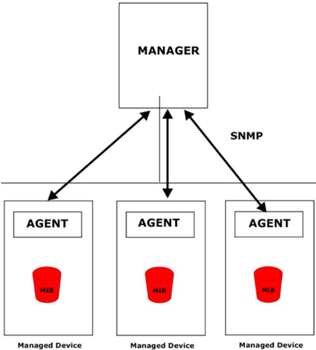
flowchart
graph TD
    A["MANAGER"] --> B["AGENT"]
    A --> C["AGENT"]
    A --> D["AGENT"]
    B --> E["MIB"]
    C --> F["MIB"]
    D --> G["MIB"]
    style A fill:#f9f9f9,stroke:#333
    style B fill:#e6f7ff,stroke:#333
    style C fill:#e6f7ff,stroke:#333
    style D fill:#e6f7ff,stroke:#333
    note right of A: SNMP
    note left of B: Managed Device
    note right of C: Managed Device
    note right of D: Managed Device
Figure 24-1 SNMP Management Model
An SNMP managed network consists of two main components: agents and a manager.
An agent is a management software module that resides in a managed device (the Prestige). An agent translates the local management information from the managed device into a form compatible with SNMP. The manager is the console through which network administrators perform network management functions. It executes applications that control and monitor managed devices.
The managed devices contain object variables/managed objects that define each piece of information to be collected about a device. Examples of variables include the number of packets received, node port status etc. A Management Information Base (MIB) is a collection of managed objects. SNMP allows a manager and agents to communicate for the purpose of accessing these objects.
SNMP itself is a simple request/response protocol based on the manager/agent model. The manager issues a request and the agent returns responses using the following protocol operations:
- Get - Allows the manager to retrieve an object variable from the agent.
- GetNext - Allows the manager to retrieve the next object variable from a table or list within an agent. In SNMPv1, when a manager wants to retrieve all elements of a table from an agent, it initiates a Get operation, followed by a series of GetNext operations.
- Set - Allows the manager to set values for object variables within an agent.
- Trap - Used by the agent to inform the manager of some events.
24.2 Supported MIBs
The Prestige supports RFC-1215 and MIB II as defined in RFC-1213 as well as ZyXEL private MIBs. The focus of the MIBs is to let administrators collect statistic data and monitor status and performance.
24.3 SNMP Configuration
To configure SNMP, select option 22 from the main menu to open Menu 22 — SNMP Configuration as shown next. The “community” for Get, Set and Trap fields is SNMP terminology for password.
Menu 22 - SNMP Configuration
SNMP:
Get Community= public
Set Community= public
Trusted Host= 0.0.0.0
Trap:
Community= public
Destination= 0.0.0.0
Press ENTER to Confirm or ESC to Cancel:
Figure 24-2 Menu 22 SNMP Configuration
The following table describes the SNMP configuration parameters.
Table 24-1 Menu 22 SNMP Configuration
| FIELD | DESCRIPTION | EXAMPLE |
| SNMP: | ||
| Get Community | Type the Get Community, which is the password for the incoming Get- and GetNext requests from the management station. | public |
| Set Community | Type the Set community, which is the password for incoming Set requests from the management station. | public |
| Trusted Host | If you enter a trusted host, your Prestige will only respond to SNMP messages from this address. A blank (default) field means your Prestige will respond to all SNMP messages it receives, regardless of source. | 0.0.0.0 |
| Trap: | ||
| Community | Type the trap community, which is the password sent with each trap to the SNMP manager. | public |
| Destination | Type the IP address of the station to send your SNMP traps to. | 0.0.0.0 |
| When you have completed this menu, press [ENTER] at the prompt “Press ENTER to confirm or ESC to cancel” to save your configuration or press [ESC] to cancel and go back to the previous screen. | ||
24.4 SNMP Traps
The Prestige will send traps to the SNMP manager when any one of the following events occurs:
Table 24-2 SNMP Traps
| TRAP # | TRAP NAME | DESCRIPTION |
| 1 | coldStart (defined in RFC-1215) | A trap is sent after booting (power on). |
| 2 | warmStart (defined in RFC-1215) | A trap is sent after booting (software reboot). |
| 3 | linkDown (defined in RFC-1215) | A trap is sent when the port is down. |
| 4 | linkUp (defined in RFC-1215) | A trap is sent when the port is up. |
| 5 | authenticationFailure (defined in RFC-1215) | A trap is sent to the manager when receiving any SNMP get or set requirements with wrong community (password). |
| 6 | whyReboot (defined in ZYXEL-MIB) | A trap is sent with the reason of restart before rebooting when the system is going to restart (warm start). |
| 6a | For intentional reboot : | A trap is sent with the message "System reboot by user!" if reboot is done intentionally, (for example, download new files, CI command "sys reboot", etc.). |
The following table maps the physical port and encapsulation to the interface type.
Table 24-3 Ports and Interface Types
| PHYSICAL PORT/ENCAP | INTERFACE TYPE |
| LAN port(s) | enet0 |
| Wireless port | enet1 |
| PPPoE encap | pppoe |
| 1483 encap | mpoa |
| Ethernet encap | enet-encap |
| PPPoA | ppp |
Chapter 25
System Security
This chapter describes how to configure the system security on the Prestige. This chapter is only applicable to the Prestige 650H and the Prestige 650HW.
25.1 System Security Overview
You can configure the system password, an external RADIUS server and IEEE802.1x in menu 23.
25.1.1 System Password
Enter 1 in the main menu to display Menu 23- System Security.
You should change the default password. If you forget your password you have to restore the default configuration file. Refer to the section on changing the system password in the Introducing the SMT chapter and the section on resetting the Prestige in the Introducing the Web Configurator chapter.
Menu 23 - System Security
1. Change Password
2. RADIUS Server
4. IEEE802.1x
Figure 25-1 Menu 23 System Security
25.1.2 Configuring External RADIUS Server
From Menu 23- System Security, enter 2 to display Menu 23.2 - System Security-RADIUS Server.
Menu 23 - System Security
1. Change Password
2. RADIUS Server
4. IEEE802.1x
Figure 25-2 Menu 23 System Security
Menu 23.2 - System Security - RADIUS Server
Authentication Server:
Active= No
Server Address= 10.11.12.13
Port #= 1812
Shared Secret= *****
Accounting Server:
Active= No
Server Address= 10.11.12.13
Port #= 1813
Shared Secret= *****
Press ENTER to Confirm or ESC to Cancel:
Figure 25-3 Menu 23.2 System Security : RADIUS Server
The following table describes the fields in this menu.
Table 25-1 Menu 23.2 System Security : RADIUS Server
| FIELD | DESCRIPTION | EXAMPLE |
| Authentication Server | ||
| Active | Press [SPACE BAR] to select Yes and press [ENTER] to enable user authentication through an external authentication server. | No |
| Server Address | Enter the IP address of the external authentication server in dotted decimal notation. | 10.11.12.13 |
| Port # | The default port of the RADIUS server for authentication is 1812.You need not change this value unless your network administrator instructs you to do so with additional information. | 1812 |
| Shared Secret | Specify a password (up to 31 alphanumeric characters) as the key to be shared between the external authentication server and the access points.The key is not sent over the network. This key must be the same on the external authentication server and Prestige. | |
| Accounting Server | ||
| Active | Press [SPACE BAR] to select Yes and press [ENTER] to enable user authentication through an external accounting server. | No |
| Server Address | Enter the IP address of the external accounting server in dotted decimal notation. | 10.11.12.13 |
Table 25-1 Menu 23.2 System Security : RADIUS Server
| FIELD | DESCRIPTION | EXAMPLE |
| Port # | The default port of the RADIUS server for accounting is 1813.You need not change this value unless your network administrator instructs you to do so with additional information. | 1813 |
| Shared Secret | Specify a password (up to 31 alphanumeric characters) as the key to be shared between the external accounting server and the access points.The key is not sent over the network. This key must be the same on the external accounting server and Prestige. | |
| When you have completed this menu, press [ENTER] at the prompt “Press ENTER to confirm or ESC to cancel” to save your configuration or press [ESC] to cancel and go back to the previous screen. | ||
25.1.3 IEEE802.1x
The IEEE802.1x standards outline enhanced security methods for both the authentication of wireless stations and encryption key management.
Follow the steps below to enable EAP authentication on your Prestige.
Step 1. From the main menu, enter 23 to display Menu23 – System Security.
Menu 23 - System Security
- Change Password
- RADIUS Server
- IEEE802.1x
Figure 25-4 Menu 23 System Security
Step 2. Enter 4 to display Menu 23.4 – System Security – IEEE802.1x.
Menu 23.4 - System Security - IEEE802.1x
Wireless Port Control= Authentication Required
ReAuthentication Timer (in second)= 1800
Idle Timeout (in second)= 3600
Authentication Databases= Local User Database Only
Press ENTER to Confirm or ESC to Cancel:
Figure 25-5 Menu 23.4 System Security : IEEE802.1x
The following table describes the fields in this menu.
Table 25-2 Menu 23.4 System Security : IEEE802.1x
| FIELD | DESCRIPTION |
| Wireless Port Control | Press [SPACE BAR] and select a security mode for the wireless LAN access.SelectNo Authentication Requiredto allow any clients access to your wired network without entering usernames and passwords. This is the default setting.SelectingAuthentication Requiredmeans clients have to enter usernames and passwords before access to the wired network is allowed.SelectNo Access Allowedto block all clients access to the wired network. |
| ReAuthentication Timer (in seconds) | Specify how often a client has to re-enter username and password to stay connected to the wired network.This field is activated only when you selectAuthentication Requiredin the Wireless Port Controlfield. Enter a time interval between 10 and 9999 (in seconds). The default time interval is1800seconds (or 30 minutes). |
| Idle Timeout | The Prestige automatically disconnects a client from the wired network after a period of inactivity. The client needs to enter the username and password again before access to the wired network is allowed.This field is activated only when you selectAuthentication Requiredin the Wireless Port Controlfield. The default time interval is3600seconds (or 1 hour). |
Table 25-2 Menu 23.4 System Security : IEEE802.1x
| FIELD | DESCRIPTION |
| Authentication Databases | This field is activated only when you select Authentication Required in the Wireless Port Control field.The authentication database contains wireless station login information. The local user database is the built-in database on the Prestige. The RADIUS is an external server. Use this field to decide which database the Prestige should use (first) to authenticate a wireless station.Before you specify the priority, make sure you have set up the corresponding database correctly first.Select Local User Database Only to have the Prestige just check the built-in user database on the Prestige for a wireless station's username and password.Select RADIUS Only to have the Prestige just check the user database on the specified RADIUS server for a wireless station's username and password.Select Local first, then RADIUS to have the Prestige first check the user database on the Prestige for a wireless station's user name and password. If the user name is not found, the Prestige checks the user database on the specified RADIUS server.Select RADIUS first, then Local to have the Prestige first check the user database on the specified RADIUS server for a wireless station's user name and password. When the user name is not found or password does not match in the RADIUS server, the Prestige will not check the local user database and the authentication fails. If the Prestige cannot reach the RADIUS server, then the Prestige checks the local user database on the Prestige. |
| When you have completed this menu, press [ENTER] at the prompt “Press ENTER to confirm or ESC to cancel” to save your configuration or press [ESC] to cancel and go back to the previous screen. | |
Once you enable user authentication, you need to specify an external RADIUS server or create local user accounts on the Prestige for authentication.
25.2 Creating User Accounts on the Prestige
By storing user profiles locally, your Prestige is able to authenticate wireless users without interacting with a network RADIUS server.
Follow the steps below to set up user profiles on your Prestige.
Step 1. From the main menu, enter 14 to display Menu 14 - Dial-in User Setup.
| Menu 14 - Dial-in User Setup | |||
| 1. _____ | 9. _____ | 17. _____ | 25. _____ |
| 2. _____ | 10. _____ | 18. _____ | 26. _____ |
| 3. _____ | 11. _____ | 19. _____ | 27. _____ |
| 4. _____ | 12. _____ | 20. _____ | 28. _____ |
| 5. _____ | 13. _____ | 21. _____ | 29. _____ |
| 6. _____ | 14. _____ | 22. _____ | 30. _____ |
| 7. _____ | 15. _____ | 23. _____ | 31. _____ |
| 8. _____ | 16. _____ | 24. _____ | 32. _____ |
| Enter Menu Selection Number: | |||
Figure 25-6 Menu 14 Dial-in User Setup
Step 3. Type a number and press [ENTER] to edit the user profile.
| Menu 14.1 - Edit Dial-in User |
| User Name= test Active= Yes Password= ********* |
| Press ENTER to Confirm or ESC to Cancel: |
Figure 25-7 Menu 14.1 Edit Dial-in User
The following table describes the fields in this menu.
Table 25-3 Menu 14.1 Edit Dial-in User
| FIELD | DESCRIPTION |
| User Name | Enter a username up to 31 alphanumeric characters long for this user profile.This field is case sensitive. |
| Active | Press [SPACE BAR] to select Yes and press [ENTER] to enable the user profile. |
| Password | Enter a password up to 31 characters long for this user profile. |
| When you have completed this menu, press [ENTER] at the prompt “Press ENTER to confirm or ESC to cancel” to save your configuration or press [ESC] to cancel and go back to the previous screen. | |
Chapter 26
System Information and Diagnosis
This chapter covers the information and diagnostic tools in SMT menus 24.1 to 24.4.
26.1 System Maintenance Overview
These tools include updates on system status, port status, log and trace capabilities and upgrades for the system software. This chapter describes how to use these tools in detail.
Type 24 in the main menu to open Menu 24 – System Maintenance, as shown in the following figure.
Menu 24 - System Maintenance
1. System Status
2. System Information and Console Port Speed
3. Log and Trace
4. Diagnostic
5. Backup Configuration
6. Restore Configuration
7. Upload Firmware
8. Command Interpreter Mode
9. Call Control
10. Time and Date Setting
11. Remote Management
Enter Menu Selection Number:
Figure 26-1 Menu 24 System Maintenance
26.2 System Status
The first selection, System Status gives you information on the status and statistics of the ports, as shown next. System Status is a tool that can be used to monitor your Prestige. Specifically, it gives you information on your ADSL telephone line status, number of packets sent and received.
To get to System Status, type 24 to go to Menu 24 — System Maintenance. From this menu, type 1. System Status. There are two commands in Menu 24.1 — System Maintenance — Status. Entering 1 resets the counters; [ESC] takes you back to the previous screen.
The following table describes the fields present in Menu 24.1 — System Maintenance — Status which are read-only and meant for diagnostic purposes.
| Menu 24.1 - System Maintenance - Status hh:mm:ss Sat. Jan. 01, 2000 | |||||||
| Node-Lnk | Status | TxPkts | RxPkts | Errors | Tx B/s | Rx B/s | Up Time |
| 1-ENET | Up | 211 | 0 | 0 | 0 | 0 | 0:26:20 |
| 2 | N/A | 0 | 0 | 0 | 0 | 0 | 0:00:00 |
| 3 | N/A | 0 | 0 | 0 | 0 | 0 | 0:00:00 |
| 4 | N/A | 0 | 0 | 0 | 0 | 0 | 0:00:00 |
| 5 | N/A | 0 | 0 | 0 | 0 | 0 | 0:00:00 |
| 6 | N/A | 0 | 0 | 0 | 0 | 0 | 0:00:00 |
| 7 | N/A | 0 | 0 | 0 | 0 | 0 | 0:00:00 |
| 8 | N/A | 0 | 0 | 0 | 0 | 0 | 0:00:00 |
| My WAN IP (from ISP) : | |||||||
Figure 26-2 Menu 24.1 System Maintenance : Status
The following table describes the fields present in Menu 24.1 — System Maintenance — Status.
Table 26-1 Menu 24.1 System Maintenance : Status
| FIELD | DESCRIPTION |
| Node-Lnk | This is the node index number and link type. Link types are: PPP, ENET, 1483. |
| Status | This shows the status of the remote node. |
| TxPkts | The number of transmitted packets to this remote node. |
| RxPkts | The number of received packets from this remote node. |
| Errors | The number of error packets on this connection. |
| Tx B/s | This shows the transmission rate in bytes per second. |
| Rx B/s | This shows the receiving rate in bytes per second. |
| Up Time | This is the time this channel has been connected to the current remote node. |
| My WAN IP (IP address) | This is the IP address of the ISP remote node. |
Table 26-1 Menu 24.1 System Maintenance : Status
| FIELD | DESCRIPTION |
| My WAN IP (from ISP) | This is the IP address of the ISP remote node. |
| Ethernet | This shows statistics for the LAN. |
| Status | This shows the current status of the LAN. |
| Tx Pkts | This is the number of transmitted packets to the LAN. |
| Rx Pkts | This is the number of received packets from the LAN. |
| Collision | This is the number of collisions. |
| WAN | This shows statistics for the WAN. |
| Line Status | This shows the current status of the xDSL line which can be Up or Down. |
| Upstream Speed | This shows the upstream transfer rate in kbps. |
| Downstream Speed | This shows the downstream transfer rate in kbps. |
| CPU Load | This specifies the percentage of CPU utilization. |
26.3 System Information
To get to the System Information :
Step 1. Enter 24 in the main menu to display Menu 24 — System Maintenance.
Step 2. Enter 2 to display Menu 24.2 — System Information.
Step 3. From this menu you have two choices as shown in the next figure:
Menu 24.2 - System Information and Console Port Speed
1. System Information
2. Console Port Speed
Please enter selection:
Figure 26-3 Menu 24.2 System Information and Console Port Speed
26.3.1 System Information
Enter 1 in menu 24.2 to display the screen shown next.
| Menu 24.2.1 - System Maintenance - Information |
| Name: |
| Routing: IP |
| ZyNOS F/W Version: V3.40(IS.2) | 6/16/2003 |
| ADSL Chipset Vendor: Alcatel, Version 3.9.122 |
| Standard: Multi-Mode |
| LAN |
| Ethernet Address: 00:a0:c5:74:55:8a |
| IP Address: 192.168.1.1 |
| IP Mask: 255.255.255.0 |
| DHCP: Server |
| Press ESC or RETURN to Exit: |
Figure 26-4 Menu 24.2.1 System Maintenance : Information
The following table describes the fields in this menu.
Table 26-2 Menu 24.2.1 System Maintenance : Information
| FIELD | DESCRIPTION |
| Name | Displays the system name of your Prestige. This information can be changed in Menu 1 – General Setup. |
| Routing | Refers to the routing protocol used. |
| ZyNOS F/W Version | Refers to the ZyNOS (ZyXEL Network Operating System) system firmware version. ZyNOS is a registered trademark of ZyXEL Communications Corporation. |
| ADSL Chipset Vendor | Displays the vendor of the ADSL chipset and DSL version. |
| Standard | This refers to the operational protocol the Prestige and the DSLAM (Digital Subscriber Line Access Multiplexer) are using. |
| LAN | |
| Ethernet Address | Refers to the Ethernet MAC (Media Access Control) of your Prestige. |
| IP Address | This is the IP address of the Prestige in dotted decimal notation. |
| IP Mask | This shows the subnet mask of the Prestige. |
Table 26-2 Menu 24.2.1 System Maintenance : Information
| FIELD | DESCRIPTION |
| DHCP | This field shows the DHCP setting (None, Relay or Server) of the Prestige. |
26.3.2 Console Port Speed
You can set up different port speeds for the console port through Menu 24.2.2 – System Maintenance – Console Port Speed. Your Prestige supports 9600 (default), 19200, 38400, 57600 and 115200 bps. Press [SPACE BAR] and then [ENTER] to select the desired speed in menu 24.2.2, as shown in the following figure.
Menu 24.2.2 - System Maintenance - Change Console Port Speed
Console Port Speed: 9600
Press ENTER to Confirm or ESC to Cancel:
Figure 26-5 Menu 24.2.2 System Maintenance : Change Console Port Speed
Once you change the Prestige consol port speed, you must also set the speed parameter for the communication software you are using to connect to the Prestige.
26.4 Log and Trace
There are two logging facilities in the Prestige. The first is the error logs and trace records that are stored locally. The second is the UNIX syslog facility for message logging.
26.4.1 Viewing Error Log
The first place you should look for clues when something goes wrong is the error log. Follow the procedures to view the local error/trace log:
Step 1. Type 24 in the main menu to display Menu 24 – System Maintenance.
Step 2. From menu 24, type 3 to display Menu 24.3 – System Maintenance – Log and Trace.
Menu 24.3 - System Maintenance - Log and Trace
1. View Error Log
2. UNIX Syslog
Please enter selection:
Figure 26-6 Menu 24.3 System Maintenance : Log and Trace
Step 3. Enter 1 from Menu 24.3 — System Maintenance — Log and Trace to display the error log in the system.
After the Prestige finishes displaying the error log, you will have the option to clear it. Samples of typical error and information messages are presented in the next figure.
59 Thu Jan 01 00:00:03 1970 PP0f INFO LAN promiscuous mode <0>
60 Thu Jan 01 00:00:03 1970 PP00 -WARN SNMP TRAP 0: cold start
61 Thu Jan 01 00:00:03 1970 PP00 INFO main: init completed
62 Thu Jan 01 00:00:19 1970 PP00 INFO SMT Session Begin
63 Thu Jan 01 00:00:24 1970 PP0a WARN MPOA Link Down
Clear Error Log (y/n):
Figure 26-7 Sample Error and Information Messages
26.4.2 Syslog and Accounting
The Prestige uses the UNIX syslog facility to log the CDR (Call Detail Record) and system messages to a syslog server. Syslog and accounting can be configured in Menu 24.3.2 — System Maintenance — UNIX Syslog, as shown next.
Menu 24.3.2 - System Maintenance - UNIX Syslog

UNIX Syslog:
Active= No
Syslog IP Address= ?
Log Facility= Local 1

Types:
CDR= No
Packet triggered= No
Filter Log= No
PPP Log= No

Press ENTER to Confirm or ESC to Cancel:

Press Space Bar to Toggle.
Figure 26-8 Menu 24.3.2 System Maintenance : Syslog and Accounting
You need to configure the UNIX syslog parameters described in the following table to activate syslog then choose what you want to log.
Table 26-3 Menu 24.3.2 System Maintenance : Syslog and Accounting
| PARAMETER | DESCRIPTION |
| UNIX Syslog: | |
| Active | Use [SPACE BAR] and then [ENTER] to turn syslog on or off. |
| Syslog IP Address | Type the IP address of your syslog server. |
| Log Facility | Use [SPACE BAR] and then [ENTER] to select one of seven different local options. The log facility lets you log the message in different server files. Refer to your UNIX manual. |
| Types: | |
| CDR | Call Detail Record (CDR) logs all data phone line activity if set to Yes. |
| Packet Triggered | The first 48 bytes or octets and protocol type of the triggering packet is sent to the UNIX syslog server when this field is set to Yes. |
| Filter Log | No filters are logged when this field is set to No. Filters with the individual filter Log Filter field set to Yes are logged when this field is set to Yes. |
| PPP Log | PPP events are logged when this field is set to Yes. |
The following are examples of the four types of syslog messages sent by the Prestige:
| 1 - CDR |
| SdcmdSyslogSend ( SYSLOG CDR, SYSLOG INFO, String); |
| String = board xx line xx channel xx, call xx, str |
| board = the hardware board ID |
| line = the WAN ID in a board |
| Channel = channel ID within the WAN |
| call = the call reference number which starts from 1 and increments by 1 for each new call |
| str = C01 Outgoing Call dev xx ch xx (dev:device No. ch:channel No.) |
| C01 Incoming Call xxxxBps xxxx (L2TP, xxxx = Remote Call ID) |
| C01 Incoming Call xxxx (= connected speed) xxxx (= Remote Call ID) |
| L02 Tunnel Connected (L2TP) |
| C02 OutCall Connected xxxx (= connected speed) xxxx (= Remote Call ID) |
| C02 CLID call refused |
| L02 Call Terminated |
| C02 Call Terminated |
| Jul 19 11:19:27 192.168.102.2 ZYXEL: board 0 line 0 channel 0, call 1, C01 Outgoing Call dev=2 ch=0 40002Jul 19 11:19:32 192.168.102.2 ZYXEL: board 0 line 0 channel 0, call 1, C02 OutCall Connected 64000 40002Jul 19 11:20:06 192.168.102.2 ZYXEL: board 0 line 0 channel 0, call 1, C02 Call Terminated |
| 2 - Packet Triggered |
| SdcmdSyslogSend (SYSLOG PKTTRI, SYSLOG NOTICE, String); |
| String = Packet trigger: Protocol=xx Data=xxxxxxxxx....x |
| Protocol: (1:IP 2:IPX 3:IPXHC 4:BPDU 5:ATALK 6:IPNG) |
| Data: We will send forty-eight Hex characters to the server |
Jul 19 11:28:39 192.168.102.2 ZYXEL: Packet Trigger: Protocol=1,
Data=4500003c100100001f010004c0a86614ca849a7b08004a5c020001006162636465666768696a6b6c6d6e6f70717273
74
Jul 19 11:28:56 192.168.102.2 ZYXEL: Packet Trigger: Protocol=1,
Data=4500002c1b0140001f06b50ec0a86614ca849a7b0427001700195b3e0000000600220008cd40000020405b4
Jul 19 11:29:06 192.168.102.2 ZYXEL: Packet Trigger: Protocol=1,
Data=45000028240140001f06ac12c0a86614ca849a7b0427001700195b451d1430135004000077600000

3 - Filter Log

SdcmdSyslogSend (SYSLOG FILLOG, SYSLOG NOTICE, String);

String = IP[Src=xx.xx.xx.xx Dst=xx.xx.xx.xx prot spo=xxxx dpo=xxxx] S04>R01mD

IP[...] is the packet header and S04>R01mD means filter set 4 (S) and rule 1 (R), match (m), drop (D).

Src: Source Address

Dst: Destination Address

prot: Protocol ("TCP", "UDP", "ICMP")

spo: Source port

dpo: Destination port

Jul 19 14:43:55 192.168.102.2 ZYXEL: IP [Src=202.132.154.123 Dst=255.255.255.255 UDP spo=0208
dpo=0208]} S03>R01mF

Jul 19 14:44:00 192.168.102.2 ZYXEL: IP [Src=192.168.102.20 Dst=202.132.154.1 UDP spo=05d4
dpo=0035]} S03>R01mF

Jul 19 14:44:04 192.168.102.2 ZYXEL: IP [Src=192.168.102.20 Dst=202.132.154.1 UDP spo=05d4
dpo=0035]} S03>R01mF

4 - PPP Log

SdcmdSyslogSend (SYSLOG PPPLOG, SYSLOG NOTICE, String);

String = ppp:Proto Starting / ppp:Proto Opening / ppp:Proto Closing / ppp:Proto Shutdown

Proto = LCP / ATCP / BACP / BCP / CBCP / CCP / CHAP/ PAP / IPCP / IPXCP

Jul 19 11:42:44 192.168.102.2 ZYXEL: ppp:LCP Closing
Jul 19 11:42:49 192.168.102.2 ZYXEL: ppp:IPCP Closing
Jul 19 11:42:54 192.168.102.2 ZYXEL: ppp:CCP Closing
26.5 Diagnostic
The diagnostic facility allows you to test the different aspects of your Prestige to determine if it is working properly. Menu 24.4 allows you to choose among various types of diagnostic tests to evaluate your system, as shown in the following figure.
Follow the procedure next to get to Diagnostic:
Step 1. From the main menu, type 24 to open Menu 24 – System Maintenance.
Step 2. From this menu, type 4. Diagnostic to open Menu 24.4 – System Maintenance – Diagnostic.
Menu 24.4 - System Maintenance - Diagnostic
xDSL System
1. Reset xDSL 21. Reboot System
22. Command Mode
TCP/IP
12. Ping Host
Enter Menu Selection Number:
Host IP Address= N/A
Figure 26-9 Menu 24.4 System Maintenance : Diagnostic
The following table describes the diagnostic tests available in menu 24.4 for and the connections.
Table 26-4 Menu 24.4 System Maintenance Menu : Diagnostic
| FIELD | DESCRIPTION |
| Reset xDSL | Re-initialize the xDSL link to the telephone company. |
| Ping Host | Ping the host to see if the links and TCP/IP protocol on both systems are working. |
| Reboot System | Reboot the Prestige. |
| Command Mode | Type the mode to test and diagnose your Prestige using specified commands. |
| Host IP Address | If you typed 12 to Ping Host, now type the address of the computer you want to ping. |
Chapter 27
Firmware and Configuration File Maintenance
This chapter tells you how to backup and restore your configuration file as well as upload new firmware and configuration files.
27.1 Filename Conventions
The configuration file (often called the romfile or rom-0) contains the factory default settings in the menus such as password, DHCP Setup, TCP/IP Setup, etc. It arrives from ZyXEL with a “rom” filename extension. Once you have customized the Prestige's settings, they can be saved back to your computer under a filename of your choosing.
ZyNOS (ZyXEL Network Operating System sometimes referred to as the “ras” file) is the system firmware and has a “bin” filename extension. With many FTP and TFTP clients, the filenames are similar to those seen next.
Only use firmware for your Prestige's specific model. Refer to the label on the bottom of your Prestige.
ftp> put firmware.bin ras
This is a sample FTP session showing the transfer of the computer file " firmware.bin" to the Prestige.
ftp> get rom-0 config.cfg
This is a sample FTP session saving the current configuration to the computer file “config.cfg”.
If your (T)FTP client does not allow you to have a destination filename different than the source, you will need to rename them as the Prestige only recognizes “rom-0” and “ras”. Be sure you keep unaltered copies of both files for later use.
The following table is a summary. Please note that the internal filename refers to the filename on the Prestige and the external filename refers to the filename not on the Prestige, that is, on your computer, local network or FTP site and so the name (but not the extension) may vary. After uploading new firmware, see the ZyNOS F/W Version field in Menu 24.2.1 – System Maintenance – Information to confirm that you have uploaded the correct firmware version. The AT command is the command you enter after you press “y” when prompted in the SMT menu to go into debug mode.
Table 27-1 Filename Conventions
| FILE TYPE | INTERNAL NAME | EXTERNAL NAME | DESCRIPTION |
| Configuration File | Rom-0 | This is the configuration filename on the Prestige. Uploading the rom-0 file replaces the entire ROM file system, including your Prestige configurations, system-related data (including the default password), the error log and the trace log. | *.rom |
| Firmware | Ras | This is the generic name for the ZyNOS firmware on the Prestige. | *.bin |
27.2 Backup Configuration
The Prestige displays different messages explaining different ways to backup, restore and upload files in menus 24.5, 24.6, 24.7.1 and 24.7.2; depending on whether you use the console port or Telnet.
Option 5 from Menu 24 – System Maintenance allows you to backup the current Prestige configuration to your computer. Backup is highly recommended once your Prestige is functioning properly. FTP is the preferred methods for backing up your current configuration to your computer since they are faster. You can also perform backup and restore using menu 24 through the console port. Any serial communications program should work fine; however, you must use Xmodem protocol to perform the download/upload and you don’t have to rename the files.
Please note that terms “download” and “upload” are relative to the computer. Download means to transfer from the Prestige to the computer, while upload means from your computer to the Prestige.
27.2.1 Backup Configuration
Follow the instructions as shown in the next screen.
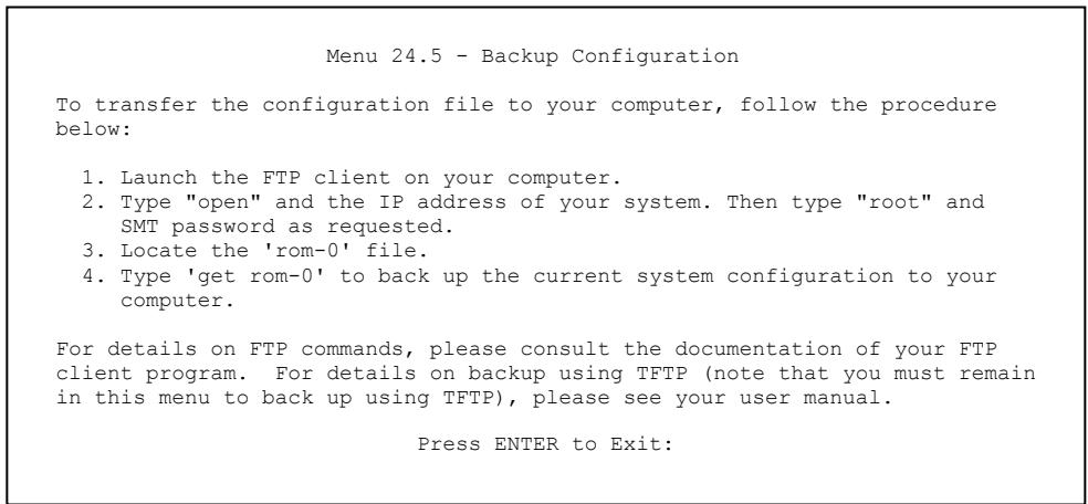
text_image
Menu 24.5 - Backup Configuration To transfer the configuration file to your computer, follow the procedure below: 1. Launch the FTP client on your computer. 2. Type "open" and the IP address of your system. Then type "root" and SMT password as requested. 3. Locate the 'rom-0' file. 4. Type 'get rom-0' to back up the current system configuration to your computer. For details on FTP commands, please consult the documentation of your FTP client program. For details on backup using TFTP (note that you must remain in this menu to back up using TFTP), please see your user manual. Press ENTER to Exit:Figure 27-1 Telnet in Menu 24.5
27.2.2 Using the FTP Command from the Command Line
Step 1. Launch the FTP client on your computer.
Step 2. Enter “open”, followed by a space and the IP address of your Prestige.
Step 3. Press [ENTER] when prompted for a username.
Step 4. Enter your password as requested (the default is “1234”).
Step 5. Enter “bin” to set transfer mode to binary.
Step 6. Use “get” to transfer files from the Prestige to the computer, for example, “get rom-0 config.rom” transfers the configuration file on the Prestige to your computer and renames it “config.rom”. See earlier in this chapter for more information on filename conventions.
Step 7. Enter “quit” to exit the ftp prompt.
27.2.3 Example of FTP Commands from the Command Line
331 Enter PASS command
Password:
230 Logged in
ftp> bin
200 Type I OK
ftp> get rom-0 zyxel.rom
200 Port command okay
150 Opening data connection for STOR ras
226 File received OK
ftp: 16384 bytes sent in 1.10Seconds 297.89Kbytes/sec.
ftp> quit
Figure 27-2 FTP Session Example
27.2.4 GUI-based FTP Clients
The following table describes some of the commands that you may see in GUI-based FTP clients.
Table 27-2 General Commands for GUI-based FTP Clients
| COMMAND | DESCRIPTION |
| Host Address | Enter the address of the host server. |
| Login Type | Anonymous.This is when a user I.D. and password is automatically supplied to the server for anonymous access. Anonymous logins will work only if your ISP or service administrator has enabled this option.Normal.The server requires a unique User ID and Password to login. |
| Transfer Type | You must use binary mode when uploading the configuration or firmware file.Transfer files in either ASCII (plain text format) or in binary mode. |
| Initial Remote Directory | Specify the default remote directory (path). |
| Initial Local Directory | Specify the default local directory (path). |
27.2.5 TFTP and FTP over WAN Will Not Work When
TFTP, FTP and Telnet over WAN will not work when:
- You have disable Telnet service in menu 24.11.
-
You have applied a filter in menu 3.1 (LAN) or in menu 11.5 (WAN) to block Telnet service.
-
The IP address in the Secured Client IP field in menu 24.11 does not match the client IP. If it does not match, the Prestige will disconnect the Telnet session immediately.
- You have an SMT console session running.
27.2.6 Backup Configuration Using TFTP
The Prestige supports the up/downloading of the firmware and the configuration file using TFTP (Trivial File Transfer Protocol) over LAN. Although TFTP should work over WAN as well, it is not recommended.
To use TFTP, your computer must have both telnet and TFTP clients. To backup the configuration file, follow the procedure shown next.
Step 1. Use telnet from your computer to connect to the Prestige and log in. Because TFTP does not have any security checks, the Prestige records the IP address of the telnet client and accepts TFTP requests only from this address.
Step 2. Put the SMT in command interpreter (CI) mode by entering 8 in Menu 24 – System Maintenance.
Step 3. Enter command “sys stdio 0” to disable the SMT timeout, so the TFTP transfer will not be interrupted. Enter command “sys stdio 5” to restore the five-minute SMT timeout (default) when the file transfer is complete.
Step 4. Launch the TFTP client on your computer and connect to the Prestige. Set the transfer mode to binary before starting data transfer.
Step 5. Use the TFTP client (see the example below) to transfer files between the Prestige and the computer. The file name for the configuration file is “rom-0” (rom-zero, not capital o).
Note that the telnet connection must be active and the SMT in CI mode before and during the TFTP transfer. For details on TFTP commands (see following example), please consult the documentation of your TFTP client program. For UNIX, use “get” to transfer from the Prestige to the computer and “binary” to set binary transfer mode.
27.2.7 TFTP Command Example
The following is an example TFTP command:
tftp [-i] host get rom-0 config.rom
where “i” specifies binary image transfer mode (use this mode when transferring binary files), “host” is the Prestige IP address, “get” transfers the file source on the Prestige (rom-0, name of the configuration file on the Prestige) to the file destination on the computer and renames it config.rom.
27.2.8 GUI-based TFTP Clients
The following table describes some of the fields that you may see in GUI-based TFTP clients.
Table 27-3 General Commands for GUI-based TFTP Clients
| COMMAND | DESCRIPTION |
| Host | Enter the IP address of the Prestige. 192.168.1.1 is the Prestige's default IP address when shipped. |
| Send/Fetch | Use “Send” to upload the file to the Prestige and “Fetch” to back up the file on your computer. |
| Local File | Enter the path and name of the firmware file (*.bin extension) or configuration file (*.rom extension) on your computer. |
| Remote File | This is the filename on the Prestige. The filename for the firmware is “ras” and for the configuration file, is “rom-0”. |
| Binary | Transfer the file in binary mode. |
| Abort | Stop transfer of the file. |
Refer to section 27.2.5 to read about configurations that disallow TFTP and FTP over WAN.
27.2.9 Backup Via Console Port (only for the Prestige 650H/HW)
Back up configuration via console port by following the HyperTerminal procedure shown next. Procedures using other serial communications programs should be similar.
Step 1. Display menu 24.5 and enter "y" at the following screen.
Ready to backup Configuration via Xmodem. Do you want to continue (y/n):
Figure 27-3 Menu 24.5 System Maintenance - Backup Configuration
Step 2. The following screen indicates that the Xmodem download has started.
You can enter ctrl-x to terminate operation any time. Starting XMODEM download...
Figure 27-4 Menu 24.5 System Maintenance – Starting Xmodem Download Screen
Step 3. Run the HyperTerminal program by clicking Transfer, then Receive File as shown in the following screen.
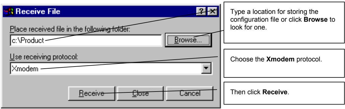
text_image
Receive File Place received file in the following folder: c:\Product Browse... Use receiving protocol: Xmodem Type a location for storing the configuration file or click Browse to look for one. Choose the Xmodem protocol. Then click Receive.Figure 27-5 Backup Configuration Example
Step 4. After a successful backup you will see the following screen. Press any key to return to the SMT menu.
** Backup Configuration completed. OK.
<h3 id="hit-any-key-to-continue">Hit any key to continue.###</h3>
Figure 27-6 Successful Backup Confirmation Screen
27.3 Restore Configuration
This section shows you how to restore a previously saved configuration. Note that this function erases the current configuration before restoring a previous back up configuration; please do not attempt to restore unless you have a backup configuration file stored on disk.
FTP is the preferred method for restoring your current computer configuration to your Prestige since FTP is faster. Please note that you must wait for the system to automatically restart after the file transfer is complete.
WARNING! DO NOT INTERRUPT THE FILE TRANSFER PROCESS AS THIS MAY PERMANENTLY DAMAGE YOUR PRESTIGE.
27.3.1 Restore Using FTP
For details about backup using (T)FTP please refer to earlier sections on FTP and TFTP file upload in this chapter.
Menu 24.6 - Restore Configuration
To transfer the firmware and the configuration file, follow the procedure below:
- Launch the FTP client on your computer.
- Type "open" and the IP address of your system. Then type "root" and SMT password as requested.
- Type "put backupfilename rom-0" where backupfilename is the name of your backup configuration file on your computer and rom-0 is the remote file name on the system. This restores the configuration to your system.
- The system reboots automatically after a successful file transfer.
For details on FTP commands, please consult the documentation of your FTP client program. For details on restoring using TFTP (note that you must remain on this menu to restore using TFTP), please see your user manual.
Press ENTER to Exit:
Figure 27-7 Telnet into Menu 24.6
Step 1. Launch the FTP client on your computer.
Step 2. Enter “open”, followed by a space and the IP address of your Prestige.
Step 3. Press [ENTER] when prompted for a username.
Step 4. Enter your password as requested (the default is “1234”).
Step 5. Enter "bin" to set transfer mode to binary.
Step 6. Find the “rom” file (on your computer) that you want to restore to your Prestige.
Step 7. Use “put” to transfer files from the Prestige to the computer, for example, “put config.rom rom-0” transfers the configuration file “config.rom” on your computer to the Prestige. See earlier in this chapter for more information on filename conventions.
Step 8. Enter “quit” to exit the ftp prompt. The Prestige will automatically restart after a successful restore process.
27.3.2 Restore Using FTP Session Example
ftp> put config.rom rom-0
200 Port command okay
150 Opening data connection for STOR rom-0
226 File received OK
221 Goodbye for writing flash
ftp: 16384 bytes sent in 0.06Seconds 273.07Kbytes/sec.
ftp>quit
Figure 27-8 Restore Using FTP Session Example
Refer to section 27.2.5 to read about configurations that disallow TFTP and FTP over WAN.
27.3.3 Restore Via Console Port (only for the Prestige 650H/HW)
Restore configuration via console port by following the HyperTerminal procedure shown next. Procedures using other serial communications programs should be similar.
Step 1. Display menu 24.6 and enter “y” at the following screen.
Ready to restore Configuration via Xmodem. Do you want to continue (y/n):
Figure 27-9 System Maintenance – Restore Configuration
Step 2. The following screen indicates that the Xmodem download has started.
Starting XMODEM download (CRC mode) ...
CCCCCC
Figure 27-10 System Maintenance – Starting Xmodem Download Screen
Step 3. Run the HyperTerminal program by clicking Transfer, then Send File as shown in the following screen.
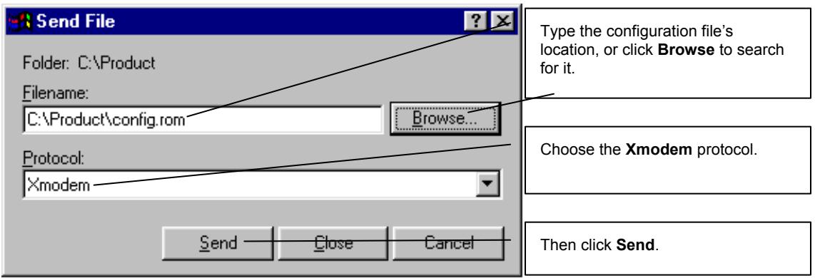
text_image
Send File Folder: C:\Product Filename: C:\Product\config.rom Browse... Protocol: Xmodem Send Close Cancel Type the configuration file's location, or click Browse to search for it. Choose the Xmodem protocol. Then click Send.Figure 27-11 Restore Configuration Example
Step 4. After a successful restoration you will see the following screen. Press any key to restart the Prestige and return to the SMT menu.
Save to ROM
Hit any key to start system reboot.
Figure 27-12 Successful Restoration Confirmation Screen
27.4 Uploading Firmware and Configuration Files
This section shows you how to upload firmware and configuration files. You can upload configuration files by following the procedure in the previous Restore Configuration section or by following the instructions in Menu 24.7.2 – System Maintenance – Upload System Configuration File (for console port).
WARNING! DO NOT INTERRUPT THE FILE TRANSFER PROCESS AS THIS MAY PERMANENTLY DAMAGE YOUR PRESTIGE.
27.4.1 Firmware File Upload
FTP is the preferred method for uploading the firmware and configuration. To use this feature, your computer must have an FTP client.
When you telnet into the Prestige, you will see the following screens for uploading firmware and the configuration file using FTP.
Menu 24.7.1 - System Maintenance - Upload System Firmware
To upload the system firmware, follow the procedure below:
- Launch the FTP client on your workstation.
- Type "open" and the IP address of your system. Then type "root" and SMT password as requested.
- Type "put firmwarefilename ras" where "firmwarefilename" is the name of your firmware upgrade file on your workstation and "ras" is the remote file name on the system.
- The system reboots automatically after a successful firmware upload.
For details on FTP commands, please consult the documentation of your FTP client program. For details on uploading system firmware using TFTP (note that you must remain on this menu to upload system firmware using TFTP), please see your manual.
Press ENTER to Exit:
Figure 27-13 Telnet Into Menu 24.7.1 Upload System Firmware
27.4.2 Configuration File Upload
You see the following screen when you telnet into menu 24.7.2.
Menu 24.7.2 - System Maintenance - Upload System Configuration File
To upload the system configuration file, follow the procedure below:
- Launch the FTP client on your workstation.
- Type "open" and the IP address of your system. Then type "root" and SMT password as requested.
- Type "put configurationfilename rom-0" where "configurationfilename" is the name of your system configuration file on your workstation, which will be transferred to the "rom-0" file on the system.
- The system reboots automatically after the upload system configuration file process is complete.
For details on FTP commands, please consult the documentation of your FTP client program. For details on uploading system firmware using TFTP (note that you must remain on this menu to upload system firmware using TFTP), please see your manual.
Press ENTER to Exit:
Figure 27-14 Telnet Into Menu 24.7.2 System Maintenance
To upload the firmware and the configuration file, follow these examples
27.4.3 FTP File Upload Command from the DOS Prompt Example
Step 1. Launch the FTP client on your computer.
Step 2. Enter “open”, followed by a space and the IP address of your Prestige.
Step 3. Press [ENTER] when prompted for a username.
Step 4. Enter your password as requested (the default is “1234”).
Step 5. Enter “bin” to set transfer mode to binary.
Step 6. Use “put” to transfer files from the computer to the Prestige, for example, “put firmware.bin ras” transfers the firmware on your computer (firmware.bin) to the Prestige and renames it “ras”. Similarly, “put config.rom rom-0” transfers the configuration file on your computer (config.rom) to the Prestige and renames it “rom-0”. Likewise “get rom-0 config.rom” transfers the configuration file on the Prestige to your computer and renames it “config.rom.” See earlier in this chapter for more information on filename conventions.
Step 7. Enter “quit” to exit the ftp prompt.
The Prestige automatically restarts after a successful file upload.
27.4.4 FTP Session Example of Firmware File Upload
331 Enter PASS command
Password:
230 Logged in
ftp> bin
200 Type I OK
ftp> put firmware.bin ras
200 Port command okay
150 Opening data connection for STOR ras
226 File received OK
ftp: 1103936 bytes sent in 1.10Seconds 297.89Kbytes/sec.
ftp> quit
Figure 27-15 FTP Session Example of Firmware File Upload
More commands (found in GUI-based FTP clients) are listed earlier in this chapter.
Refer to section 27.2.5 to read about configurations that disallow TFTP and FTP over WAN.
27.4.5 TFTP File Upload
The Prestige also supports the uploading of firmware files using TFTP (Trivial File Transfer Protocol) over LAN. Although TFTP should work over WAN as well, it is not recommended.
To use TFTP, your computer must have both telnet and TFTP clients. To transfer the firmware and the configuration file, follow the procedure shown next.
Step 1. Use telnet from your computer to connect to the Prestige and log in. Because TFTP does not have any security checks, the Prestige records the IP address of the telnet client and accepts TFTP requests only from this address.
Step 2. Put the SMT in command interpreter (CI) mode by entering 8 in Menu 24 – System Maintenance.
Step 3. Enter the command “sys stdio 0” to disable the console timeout, so the TFTP transfer will not be interrupted. Enter “command sys stdio 5” to restore the five-minute console timeout (default) when the file transfer is complete.
Step 4. Launch the TFTP client on your computer and connect to the Prestige. Set the transfer mode to binary before starting data transfer.
Step 5. Use the TFTP client (see the example below) to transfer files between the Prestige and the computer. The file name for the firmware is “ras”.
Note that the telnet connection must be active and the Prestige in CI mode before and during the TFTP transfer. For details on TFTP commands (see following example), please consult the documentation of your TFTP client program. For UNIX, use “get” to transfer from the Prestige to the computer, “put” the other way around, and “binary” to set binary transfer mode.
27.4.6 TFTP Upload Command Example
The following is an example TFTP command:
tftp [-i] host put firmware.bin ras
where “i” specifies binary image transfer mode (use this mode when transferring binary files), “host” is the Prestige’s IP address and “put” transfers the file source on the computer (firmware.bin – name of the firmware on the computer) to the file destination on the remote host (ras - name of the firmware on the Prestige).
Commands that you may see in GUI-based TFTP clients are listed earlier in this chapter.
27.4.7 Uploading Via Console Port (only for the Prestige 650H/HW)
FTP or TFTP are the preferred methods for uploading firmware to your Prestige. However, in the event of your network being down, uploading files is only possible with a direct connection to your Prestige via the console port. Uploading files via the console port under normal conditions is not recommended since FTP or TFTP is faster. Any serial communications program should work fine; however, you must use the Xmodem protocol to perform the download/upload.
27.4.8 Uploading Firmware File Via Console Port (only for the Prestige 650H/HW)
Step 1. Select 1 from Menu 24.7 – System Maintenance – Upload Firmware to display Menu 24.7.1 – System Maintenance – Upload System Firmware, then follow the instructions as shown in the following screen.
Menu 24.7.1 - System Maintenance - Upload System Firmware
To upload system firmware:
1. Enter "y" at the prompt below to go into debug mode.
2. Enter "atur" after "Enter Debug Mode" message.
3. Wait for "Starting XMODEM upload" message before activating Xmodem upload on your terminal.
4. After successful firmware upload, enter "atgo" to restart the Prestige.
Warning: Proceeding with the upload will erase the current system firmware.
Do You Wish To Proceed: (Y/N)
Figure 27-16 Menu 24.7.1 as seen using the Console Port
Step 2. After the "Starting Xmodem upload" message appears, activate the Xmodem protocol on your computer. Follow the procedure as shown previously for the HyperTerminal program. The procedure for other serial communications programs should be similar.
27.4.9 Example Xmodem Firmware Upload Using HyperTerminal
Click Transfer, then Send File to display the following screen.
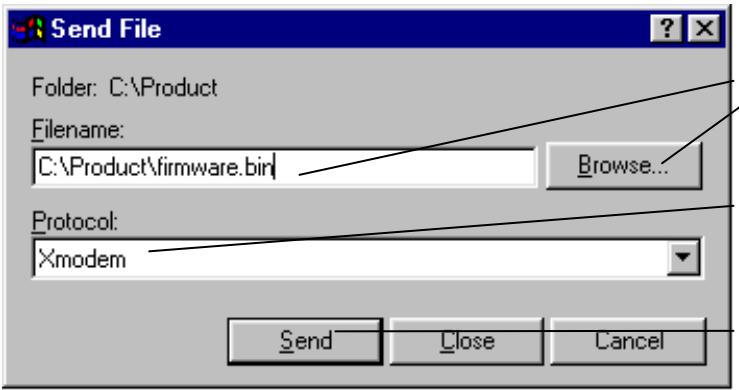
text_image
Send File Folder: C:\Product Filename: C:\Product\firmware.bin Browse... Protocol: Xmodem Send Close CancelType the firmware file's location, or click Browse to look for it.
Choose the Xmodem protocol.
Then click Send.
Figure 27-17 Example Xmodem Upload
After the configuration upload process has completed, restart the Prestige by entering “atgo”.
27.4.10 Uploading Configuration File Via Console Port
Step 1. Select 2 from Menu 24.7 – System Maintenance – Upload Firmware to display Menu 24.7.2 – System Maintenance – Upload System Configuration File. Follow the instructions as shown in the next screen.
Menu 24.7.2 - System Maintenance - Upload System Configuration File
To upload system configuration file:
1. Enter "y" at the prompt below to go into debug mode.
2. Enter "atlc" after "Enter Debug Mode" message.
3. Wait for "Starting XMODEM upload" message before activating Xmodem upload on your terminal.
4. After successful firmware upload, enter "atgo" to restart the system.
Warning:
1. Proceeding with the upload will erase the current configuration file.
2. The system's console port speed (Menu 24.2.2) may change when it is restarted; please adjust your terminal's speed accordingly. The password may change (menu 23), also.
3. When uploading the DEFAULT configuration file, the console port speed will be reset to 9600 bps and the password to "1234".
Do You Wish To Proceed: (Y/N)
Figure 27-18 Menu 24.7.2 as seen using the Console Port
Step 2. After the "Starting Xmodem upload" message appears, activate the Xmodem protocol on your computer. Follow the procedure as shown previously for the HyperTerminal program. The procedure for other serial communications programs should be similar.
Step 3. Enter “atgo” to restart the Prestige.
27.4.11 Example Xmodem Configuration Upload Using HyperTerminal
Click Transfer, then Send File to display the following screen.
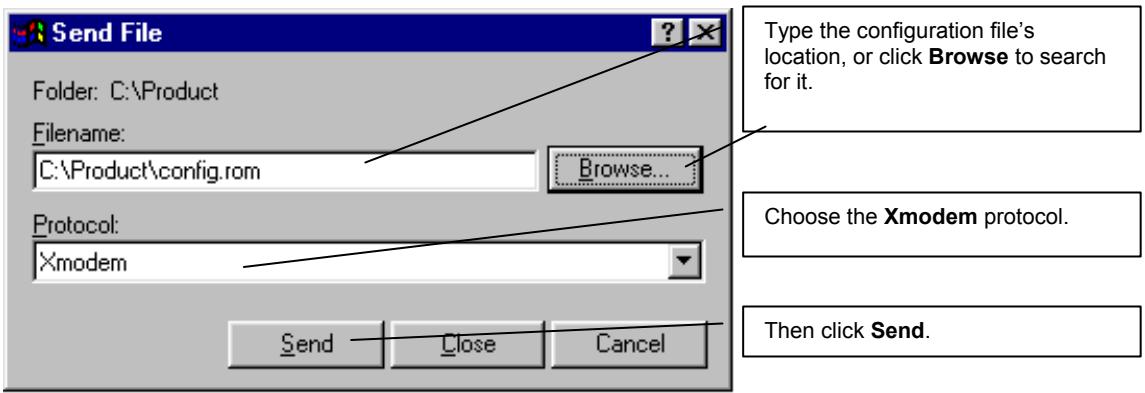
text_image
Send File Folder: C:\Product Filename: C:\Product\config.rom Browse... Protocol: Xmodem Send Close Cancel Type the configuration file's location, or click Browse to search for it. Choose the Xmodem protocol. Then click Send.Figure 27-19 Example Xmodem Upload
After the configuration upload process has completed, restart the Prestige by entering “atgo”.
Chapter 28
System Maintenance
This chapter leads you through SMT menus 24.8 to 24.10.
28.1 Command Interpreter Mode Overview
The Command Interpreter (CI) is a part of the main system firmware. The CI provides much of the same functionality as the SMT, while adding some low-level setup and diagnostic functions. Enter the CI from the SMT by selecting menu 24.8. See the included disk or the zyxel.com web site for more detailed information on CI commands. Enter 8 from Menu 24 — System Maintenance. A list of valid commands can be found by typing help or ? at the command prompt. Type “exit” to return to the SMT main menu when finished.
Menu 24 - System Maintenance
1. System Status
2. System Information and Console Port Speed
3. Log and Trace
4. Diagnostic
5. Backup Configuration
6. Restore Configuration
7. Upload Firmware
8. Command Interpreter Mode
9. Call Control
10. Time and Date Setting
11. Remote Management
Enter Menu Selection Number:
Figure 28-1 Command Mode in Menu 24
| Copyright (c) 1994 - 2003 ZyXEL Communications Corp. | |||
| ras> ? | |||
| Valid commands are: | |||
| sys | exit | device | ether |
| wan | poe | wlan | ip |
| ppp | bridge | hdap | bm |
| radius | 8021x | ||
| ras> | |||
Figure 28-2 Valid Commands
28.2 Call Control Support
Call Control Support is only applicable when Encapsulation is set to PPPoE in menu 4 or menu 11.1.
The budget management function allows you to set a limit on the total outgoing call time of the Prestige within certain times. When the total outgoing call time exceeds the limit, the current call will be dropped and any future outgoing calls will be blocked.
To access the call control menu, select option 9 in menu 24 to go to Menu 24.9 — System Maintenance — Call Control, as shown in the next table.
| Menu 24.9 - System Maintenance - Call Control |
| 1. Budget Management |
| Enter Menu Selection Number: |
Figure 28-3 Menu 24.9 System Maintenance : Call Control
28.2.1 Budget Management
Menu 24.9.1 shows the budget management statistics for outgoing calls. Enter 1 from Menu 24.9 — System Maintenance — Call Control to bring up the following menu.
| Menu 24.9.1 - Budget Management | ||
| Remote Node | Connection Time/Total Budget | Elapsed Time/Total Period |
| 1. MyISP | No Budget | No Budget |
| 2. _____ | _____ | _____ |
| 3. _____ | _____ | _____ |
| 4. _____ | _____ | _____ |
| 5. _____ | _____ | _____ |
| 6. _____ | _____ | _____ |
| 7. _____ | _____ | _____ |
| 8. _____ | _____ | _____ |
| Reset Node (0 to update screen): | ||
Figure 28-4 Menu 24.9.1 Budget Management
The total budget is the time limit on the accumulated time for outgoing calls to a remote node. When this limit is reached, the call will be dropped and further outgoing calls to that remote node will be blocked. After each period, the total budget is reset. The default for the total budget is 0 minutes and the period is 0 hours, meaning no budget control. You can reset the accumulated connection time in this menu by entering the index of a remote node. Enter 0 to update the screen. The budget and the reset period can be configured in menu 11.1 for the remote node when PPPoE encapsulation is selected.
Table 28-1 Menu 24.9.1 Budget Management
| FIELD | DESCRIPTION | EXAMPLE |
| Remote Node | Enter the index number of the remote node you want to reset (just one in this case) | 1 |
| Connection Time/Total Budget | This is the total connection time that has gone by (within the allocated budget that you set in menu 11.1. | 5/10 means that 5 minutes out of a total allocation of 10 minutes have lapsed. |
| Elapsed Time/Total Period | The period is the time cycle in hours that the allocation budget is reset (see menu 11.1.) The elapsed time is the time used up within this period. | 0.5/1 means that 30 minutes out of the 1 hour time period has lapsed. |
| Enter “0” to update the screen or press [ESC] to return to the previous screen. | ||
28.3 Time and Date Setting
The Prestige keeps track of the time and date. There is also a software mechanism to set the time manually or get the current time and date from an external server when you turn on your Prestige. Menu 24.10 allows you to update the time and date settings of your Prestige. The real time is then displayed in the Prestige error logs.
Select menu 24 in the main menu to open Menu 24 System Maintenance, as shown next.
Menu 24 - System Maintenance
1. System Status
2. System Information
3. Log and Trace
4. Diagnostic
5. Backup Configuration
6. Restore Configuration
7. Upload Firmware
8. Command Interpreter Mode
9. Call Control
10. Time and Date Setting
11. Remote Management
Enter Menu Selection Number:
Figure 28-5 Menu 24 System Maintenance
Then enter 10 to go to Menu 24.10 System Maintenance Time and Date Setting to update the time and date settings of your Prestige as shown in the following screen.
Menu 24.10 - System Maintenance - Time and Date Setting
Use Time Server when Bootup= None
Time Server Address= N/A
Current Time: 00 : 00 : 00
New Time (hh:mm:ss): 11 : 23 : 16
Current Date: 2000 - 01 - 01
New Date (yyyy-mm-dd): 2001 - 03 - 01
Time Zone= GMT
Daylight Saving= No
Start Date (mm-dd): 01 - 00
End Date (mm_dd): 01 - 00
Press ENTER to Confirm or ESC to Cancel:
Figure 28-6 Menu 24.10 System Maintenance: Time and Date Setting
Table 28-2 Menu 24.10 System Maintenance: Time and Date Setting
| FIELD | DESCRIPTION |
| Use Time Server when Bootup | Enter the time service protocol that your time server sends when you turn on the Prestige. Not all time servers support all protocols, so you may have to check with your ISP/network administrator or use trial and error to find a protocol that works. The main differences between them are the format.Daytime (RFC 867) format is day/month/year/time zone of the server.Time (RFC-868) format displays a 4-byte integer giving the total number of seconds since 1970/1/1 at 0:0:0.NTP (RFC-1305) is similar to Time (RFC-868).None. The default, enter the time manually. |
| Time Server Address | Enter the IP address or domain name of your time server. Check with your ISP/network administrator if you are unsure of this information. |
| Current Time New Time | This field displays an updated time only when you reenter this menu.Enter the new time in hour, minute and second format. |
| Current Date New Date | This field displays an updated date only when you re-enter this menu.Enter the new date in year, month and day format. |
| Time Zone | Press [SPACE BAR] and then [ENTER] to set the time difference between your time zone and Greenwich Mean Time (GMT). |
| Daylight Saving Start Date End Date | If you use daylight savings time, then choose Yes.If using daylight savings time, enter the month and day that it starts on.If using daylight savings time, enter the month and day that it ends on |
| Once you have filled in this menu, press [ENTER] at the message “Press ENTER to Confirm or ESC to Cancel” to save your configuration, or press [ESC] to cancel. | |
28.3.1 Resetting the Time
The Prestige resets the time in three instances:
i. On leaving menu 24.10 after making changes.
ii. When the Prestige starts up, if there is a time server configured in menu 24.10.
iii. 24-hour intervals after starting.
Chapter 29
Remote Management
This chapter covers remote management (SMT menu 24.11). Remote management is not available on all models.
29.1 Remote Management Overview
Remote management allows you to determine which services/protocols can access which Prestige interface (if any) from which computers.
29.2 Configuring Remote Management
To disable remote management of a service, select Disable in the corresponding Server Access field.
Enter 11 from menu 24 to display Menu 24.11 — Remote Management Control.
29.2.1 Remote Management Setup
You may manage your Prestige from a remote location via:
the Internet (WAN only), the LAN only, All (LAN and WAN) or Disable (neither).
WAN only (Internet)
ALL (LAN and WAN)
LAN only
▶ Disable (Neither)
If you enable remote management of a service, but have applied a filter to block the service, then you will not be able to remotely manage the service.
Enter 11, from menu 24, to display Menu 24.11 — Remote Management Control (shown next).
Menu 24.11 - Remote Management Control
TELNET Server:
Server Port = 23 Server Access = LAN only
Secured Client IP = 0.0.0.0
FTP Server:
Server Port = 21 Server Access = LAN only
Secured Client IP = 0.0.0.0
Web Server:
Server Port = 80 Server Access = LAN only
Secured Client IP = 0.0.0.0
Press ENTER to Confirm or ESC to Cancel:
Figure 29-1 Menu 24.11 Remote Management Control
The following table describes the fields in this menu.
Table 29-1 Menu 24.11 Remote Management Control
| FIELD | DESCRIPTION | EXAMPLE |
| Telnet ServerFTP ServerWeb Server | Each of these read-only labels denotes a service that you may use to remotely manage the Prestige. | |
| Server Port | This field shows the port number for the remote management service. You may change the port number for a service if needed, but you must use the same port number to use that service for remote management. | 23 |
| Server Access | Select the access interface (if any) by pressing the [SPACE BAR]. Choices are: LAN only, WAN only, All or Disable. The default is LAN only. | LAN only |
| Secured Client IP | The default 0.0.0.0 allows any client to use this service to remotely manage the Prestige. Enter an IP address to restrict access to a client with a matching IP address. | 0.0.0.0 |
| Once you have filled in this menu, press [ENTER] at the message "Press ENTER to Confirm or ESC to Cancel" to save your configuration, or press [ESC] to cancel. | ||
29.2.2 Remote Management Limitations
Remote management over LAN or WAN will not work when:
- A filter in menu 3.1 (LAN) or in menu 11.5 (WAN) is applied to block a Telnet, FTP or Web service.
- You have disabled that service in menu 24.11.
- The IP address in the Secured Client IP field (menu 24.11) does not match the client IP address. If it does not match, the Prestige will disconnect the session immediately.
- There is already another remote management session of the same type (Telnet, FTP or Web) running. You may only have one remote management session of the same type running at one time.
- There is a web remote management session running with a Telnet session. A Telnet session will be disconnected if you begin a web session; it will not begin if there already is a web session.
29.3 Remote Management and NAT
When NAT is enabled:
Use the Prestige's WAN IP address when configuring from the WAN.
Use the Prestige's LAN IP address when configuring from the LAN.
29.4 System Timeout
There is a system timeout of five minutes (300 seconds) for Telnet/web/FTP connections. Your Prestige will automatically log you out if you do nothing in this timeout period, except when it is continuously updating the status in menu 24.1 or when sys stdio has been changed on the command line.
Chapter 30
IP Policy Routing
This chapter covers setting and applying policies used for IP routing.
30.1 IP Policy Routing Overview
Traditionally, routing is based on the destination address only and the IAD takes the shortest path to forward a packet. IP Routing Policy (IPPR) provides a mechanism to override the default routing behavior and alter the packet forwarding based on the policy defined by the network administrator. Policy-based routing is applied to incoming packets on a per interface basis, prior to the normal routing.
30.2 Benefits of IP Policy Routing
- Source-Based Routing – Network administrators can use policy-based routing to direct traffic from different users through different connections.
- Quality of Service (QoS) – Organizations can differentiate traffic by setting the precedence or TOS (Type of Service) values in the IP header at the periphery of the network to enable the backbone to prioritize traffic.
- Cost Savings – IPPR allows organizations to distribute interactive traffic on high-bandwidth, high-cost paths while using low-cost paths for batch traffic.
- Load Sharing – Network administrators can use IPPR to distribute traffic among multiple paths.
30.3 Routing Policy
Individual routing policies are used as part of the overall IPPR process. A policy defines the matching criteria and the action to take when a packet meets the criteria. The action is taken only when all the criteria are met. The criteria includes the source address and port, IP protocol (ICMP, UDP, TCP, etc.), destination address and port, TOS and precedence (fields in the IP header) and length. The inclusion of length criterion is to differentiate between interactive and bulk traffic. Interactive applications, for example, telnet, tend to have short packets, while bulk traffic, for example, file transfer, tends to have large packets.
The actions that can be taken include:
- routing the packet to a different gateway (and hence the outgoing interface).
- setting the TOS and precedence fields in the IP header.
IPPR follows the existing packet filtering facility of RAS in style and in implementation. The policies are divided into sets, where related policies are grouped together. A user defines the policies before applying them to an interface or a remote node, in the same fashion as the filters. There are 12 policy sets with six policies in each set.
30.4 IP Routing Policy Setup
Menu 25 shows all the policies defined.
| Menu 25 - IP Routing Policy Setup | |||
| Policy Set # | Name | Policy Set # | Name |
| 1 | test | 7 | _ |
| 2 | _ | 8 | _ |
| 3 | _ | 9 | _ |
| 4 | _ | 10 | _ |
| 5 | _ | 11 | _ |
| 6 | _ | 12 | _ |
| Enter Policy Set Number to Configure= 0 | |||
| Edit Name= N/A | |||
| Press ENTER to Confirm or ESC to Cancel: | |||
Figure 30-1 Menu 25 IP Routing Policy Setup
To setup a routing policy, perform the following procedures:
Step 1. Type 25 in the main menu to open Menu 25 – IP Routing Policy Setup.
Step 2. Type the index of the policy set you want to configure to open Menu 25.1 – IP Routing Policy Setup.
Menu 25.1 shows the summary of a policy set, including the criteria and the action of a single policy, and whether a policy is active or not. Each policy contains two lines. The former part is the criteria of the incoming packet and the latter is the action. Between these two parts, separator “|” means the action is taken on criteria matched and separator “=” means the action is taken on criteria not matched.
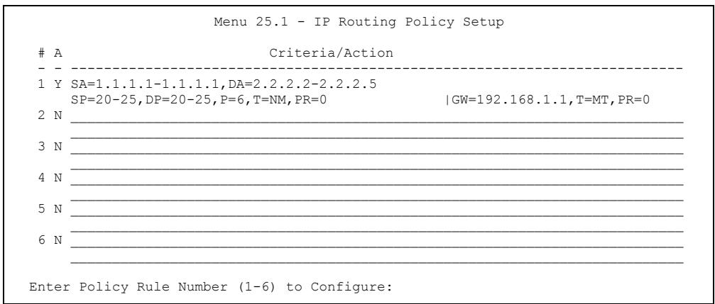
text_image
Menu 25.1 - IP Routing Policy SetupA Criteria/Action
- ----- 1 Y SA=1.1.1.1-1.1.1.1,DA=2.2.2.2-2.2.2.5 SP=20-25,DP=20-25,P=6,T=NM,PR=0 |GW=192.168.1.1,T=MT,PR=0 2 N 3 N 4 N 5 N 6 N Enter Policy Rule Number (1-6) to Configure:Figure 30-2 Menu 25.1 IP Routing Policy Setup
Table 30-1 Menu 25.1 IP Routing Policy Setup
| ABBREVIATION | MEANING | |
| Criterion | SA | Source IP Address |
| SP | Source Port | |
| DA | Destination IP Address | |
| DP | Destination Port | |
| P | IP layer 4 protocol number (TCP=6, UDP=17...) | |
| T | Type of service of incoming packet | |
| PR | Precedence of incoming packet | |
| Action | GW | Gateway IP address |
| T | Outgoing Type of service | |
| P | Outgoing Precedence | |
| Service | NM | Normal |
| MD | Minimum Delay | |
| MT | Maximum Throughput | |
| MR | Maximum Reliability | |
| MC | Minimum Cost | |
Type a number from 1 to 6 to display Menu 25.1.1 – IP Routing Policy (see the next figure). This menu allows you to configure a policy rule.
Menu 25.1.1 - IP Routing Policy
Policy Set Name= test
Active= Yes
Criteria:
    IP Protocol = 6
    Type of Service= Normal Packet length= 40
    Precedence = 0 Len Comp= N/A
    Source:
    addr start= 1.1.1.1 end= 1.1.1.1
    port start= 20 end= 20
    Destination:
    addr start= 2.2.2.2 end= 2.2.2.2
    port start= 20 end= 20
Action= Matched
Gateway addr = 192.168.1.1 Log= No
Type of Service= Max Thruput
Precedence = 0
Press ENTER to Confirm or ESC to Cancel:
Press Space Bar to Toggle.
Figure 30-3 Menu 25.1.1 IP Routing Policy
The following table describes the fields in this menu.
Table 30-2 Menu 25.1.1 IP Routing Policy
| FIELD | DESCRIPTION |
| Policy Set Name | This is the policy set name assigned in Menu 25 – IP Routing Policy Setup. |
| Active | Press [SPACE BAR] and then [ENTER] to select Yes to activate or No to deactivate the policy. Inactive policies are displayed with a minus sign “-” in SMT menu 25. |
| Criteria : | |
| IP Protocol | IP layer 4 protocol, for example, UDP, TCP, ICMP, etc. |
| Type of Service | Prioritize incoming network traffic by choosing from Don’t Care, Normal, Min Delay, Max Thruput, Min Cost or Max Reliable. |
| Precedence | Precedence value of the incoming packet. Press [SPACE BAR] and then [ENTER] to select a value from 0 to 7 or Don’t Care. |
| Packet Length | Type the length of incoming packets (in bytes). The operators in the Len Comp (next field) apply to packets of this length. |
Table 30-2 Menu 25.1.1 IP Routing Policy
| FIELD | DESCRIPTION |
| Len Comp | Press [SPACE BAR] and then [ENTER] to choose from Equal, Not Equal, Less, Greater, Less or Equal or Greater or Equal. |
| Source: | |
| addr start / end | Source IP address range from start to end. |
| port start / end | Source port number range from start to end; applicable only for TCP/UDP. |
| Destination: | |
| addr start / end | Destination IP address range from start to end. |
| port start / end | Destination port number range from start to end; applicable only for TCP/UDP. |
| Action | Specifies whether action should be taken on criteria Matched or Not Matched. |
| Gateway addr | Defines the outgoing gateway address. The gateway must be on the same subnet as the Prestige if it is on the LAN, otherwise, the gateway must be the IP address of a remote node. The default gateway is specified as 0.0.0.0. |
| Type of Service | Set the new TOS value of the outgoing packet. Prioritize incoming network traffic by choosing No Change, Normal, Min Delay, Max Thruput, Max Reliable or Min Cost. |
| Precedence | Set the new outgoing packet precedence value. Values are 0 to 7 or No Change. |
| Log | Press [SPACE BAR] and then [ENTER] to select Yes to make an entry in the system log when a policy is executed. |
| When you have completed this menu, press [ENTER] at the prompt “Press ENTER to confirm or ESC to cancel” to save your configuration or press [ESC] to cancel and go back to the previous screen. | |
30.5 Applying an IP Policy
This section shows you where to apply the IP policies after you design them.
30.5.1 Ethernet IP Policies
From Menu 3 — Ethernet Setup, type 2 to go to Menu 3.2 — TCP/IP and DHCP Ethernet Setup.
You can choose up to four IP policy sets (from 12) by typing their numbers separated by commas, for example, 2, 4, 7, 9.
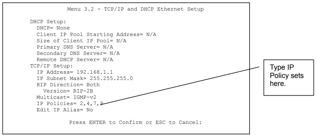
text_image
Menu 3.2 - TCP/IP and DHCP Ethernet Setup DHCP Setup: DHCP= None Client IP Pool Starting Address= N/A Size of Client IP Pool= N/A Primary DNS Server= N/A Secondary DNS Server= N/A Remote DHCP Server= N/A TCP/IP Setup: IP Address= 192.168.1.1 IP Subnet Mask= 255.255.255.0 RIP Direction= Both Version= RIP-2B Multicast= IGMP-v2 IP Policies= 2,4,7,9 Edit IP Alias= No Press ENTER to Confirm or ESC to Cancel:Figure 30-4 Menu 3.2 TCP/IP and DHCP Ethernet Setup
Go to menu 11.3 (shown next) and type the number(s) of the IP Routing Policy set(s) as appropriate. You can cascade up to four policy sets by typing their numbers separated by commas.
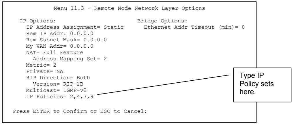
text_image
Menu 11.3 - Remote Node Network Layer Options IP Options: IP Address Assignment= Static Bridge Options: Rem IP Addr: 0.0.0.0 Ethernet Addr Timeout (min)= 0 Rem Subnet Mask= 0.0.0.0 My WAN Addr= 0.0.0.0 NAT= Full Feature Address Mapping Set= 2 Metric= 2 Private= No RIP Direction= Both Version= RIP-2B Multicast= IGMP-v2 IP Policies= 2,4,7,9 Press ENTER to Confirm or ESC to Cancel: Type IP Policy sets here:Figure 30-5 Menu 11.3 Remote Node Network Layer Options
30.6 IP Policy Routing Example
If a network has both Internet and remote node connections, you can route Web packets to the Internet using one policy and route FTP packets to a remote network using another policy. See the next figure.
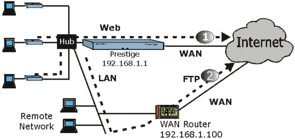
flowchart
graph TD
    A["Computer"] --> B["Hub"]
    C["Computer"] --> B
    D["Computer"] --> B
    B --> E["Web"]
    E --> F["Prestige 192.168.1.1"]
    F --> G["WAN"]
    G --> H["Internet"]
    I["Remote Network"] --> J["WAN Router 192.168.1.100"]
    J --> K["FTP 2"]
    K --> H
    style A fill:#f9f,stroke:#333
    style C fill:#f9f,stroke:#333
    style D fill:#f9f,stroke:#333
    style I fill:#ccf,stroke:#333
    style J fill:#ccf,stroke:#333
    style K fill:#ccf,stroke:#333
    style_L["LAN"] -.-> M["LAN"]
    M -.-> N["Web"]

text_image
1 Default IP Route 2 Configured IP RouteFigure 30-6 Example of IP Policy Routing
To force Web packets coming from clients with IP addresses of 192.168.1.33 to 192.168.1.64 to be routed to the Internet via the WAN port of the Prestige, follow the steps as shown next.
Step 1. Create a routing policy set in menu 25.
Step 2. Create a rule for this set in Menu 25.1.1 — IP Routing Policy as shown next.
Menu 25.1.1 - IP Routing Policy
Policy Set Name= set1
Active= Yes
Criteria:
IP Protocol = 6
Type of Service= Don't Care Packet length= 10
Precedence = Don't Care Len Comp= N/A
Source:
addr start= 192.168.1.2 end= 192.168.1.64
port start= 0 end= N/A
Destination:
addr start= 0.0.0.0 end= N/A
port start= 80 end= 80
Action= Matched
Gateway addr = 192.168.1.1 Log= No
Type of Service= No Change
Precedence = No Change
Press ENTER to Confirm or ESC to Cancel:
Press Space Bar to Toggle.
Figure 30-7 IP Routing Policy Example
Step 3. Check Menu 25.1 — IP Routing Policy Setup to see if the rule is added correctly.
Step 4. Create another policy set in menu 25.
Step 5. Create a rule in menu 25.1 for this set to route packets from any host (IP=0.0.0.0 means any host) with protocol TCP and port FTP access through another gateway (192.168.1.100).
Menu 25.1.1 - IP Routing Policy
Policy Set Name= set2
Active= Yes
Criteria:
    IP Protocol = 6
    Type of Service= Don't Care Packet length= 10
    Precedence = Don't Care Len Comp= N/A
    Source:
    addr start= 0.0.0.0 end= N/A
    port start= 0 end= N/A
    Destination:
    addr start= 0.0.0.0 end= N/A
    port start= 20 end= 21
Action= Matched
Gateway addr =192.168.1.100 Log= No
Type of Service= No Change
Precedence = No Change
Press ENTER to Confirm or ESC to Cancel:
Press Space Bar to Toggle.
Figure 30-8 IP Routing Policy Example
Step 6. Check Menu 25.1 — IP Routing Policy Setup to see if the rule is added correctly.
Step 7. Apply both policy sets in menu 3.2 as shown next.
Menu 3.2 - TCP/IP and DHCP Ethernet Setup

DHCP Setup
    DHCP= Server
    Client IP Pool Starting Address= 192.168.1.33
    Size of Client IP Pool= 64
    Primary DNS Server= 0.0.0.0
    Secondary DNS Server= 0.0.0.0
    Remote DHCP Server= N/A
TCP/IP Setup:
    IP Address= 192.168.1.1
    IP Subnet Mask= 255.255.255.0
    RIP Direction= Both
    Version= RIP-1
    Multicast= None
    IP Policies= 1,2
    Edit IP Alias= No

Press ENTER to Confirm or ESC to Cancel:

Press Space Bar to Toqgle.
Figure 30-9 Applying IP Policies Example
Chapter 31
Call Scheduling
Call scheduling (applicable for PPPoA or PPPoE encapsulation only) allows you to dictate when a remote node should be called and for how long.
31.1 Call Scheduling Overview
The call scheduling feature allows the Prestige to manage a remote node and dictate when a remote node should be called and for how long. This feature is similar to the scheduler in a video cassette recorder (you can specify a time period for the VCR to record). You can apply up to 4 schedule sets in Menu 11.1 — Remote Node Profile. From the main menu, enter 26 to access Menu 26 — Schedule Setup as shown next.
| Menu 26 - Schedule Setup | |||
| Schedule Set # | Name | Schedule Set # | Name |
| 1 | AlwaysOn | 7 | |
| 2 | 8 | ||
| 3 | 9 | ||
| 4 | 10 | ||
| 5 | 11 | ||
| 6 | 12 | ||
| Enter Schedule Set Number to Configure= | |||
| Edit Name= | |||
| Press ENTER to Confirm or ESC to Cancel: | |||
Figure 31-1 Menu 26 Schedule Setup
Lower numbered sets take precedence over higher numbered sets thereby avoiding scheduling conflicts. For example, if sets 1, 2, 3 and 4 in are applied in the remote node then set 1 will take precedence over set 2, 3 and 4 as the Prestige, by default, applies the lowest numbered set first. Set 2 will take precedence over set 3 and 4, and so on.
You can design up to 12 schedule sets but you can only apply up to four schedule sets for a remote node.
To delete a schedule set, enter the set number and press [SPACE BAR] and then [ENTER] (or delete) in the Edit Name field.
To setup a schedule set, select the schedule set you want to setup from menu 26 (1-12) and press [ENTER] to see Menu 26.1 — Schedule Set Setup as shown next.
Menu 26.1 - Schedule Set Setup
Active= Yes
Start Date(yyyy/mm/dd) = 2000 - 01 - 01
How Often= Once
Once:
Date(yyyy/mm/dd)= 2000 - 01 - 01
Weekdays:
Sunday= N/A
Monday= N/A
Tuesday= N/A
Wednesday= N/A
Thursday= N/A
Friday= N/A
Saturday= N/A
Start Time (hh:mm)= 00 : 00
Duration (hh:mm)= 00 : 00
Action= Forced On

Press ENTER to Confirm or ESC to Cancel:
Press Space Bar to Toggle
Figure 31-2 Menu 26.1 Schedule Set Setup
If a connection has been already established, your Prestige will not drop it. Once the connection is dropped manually or it times out, then that remote node can't be triggered up until the end of the Duration.
Table 31-1 Menu 26.1 Schedule Set Setup
| FIELD | DESCRIPTION | EXAMPLE |
| Active | Press [SPACE BAR] to select Yes or No. Choose Yes and press [ENTER] to activate the schedule set. | Yes |
| Start Date | Enter the start date when you wish the set to take effect in year - month-date format. Valid dates are from the present to 2036-February-5. | 2000-01-01 |
Table 31-1 Menu 26.1 Schedule Set Setup
| FIELD | DESCRIPTION | EXAMPLE |
| How Often | Should this schedule set recur weekly or be used just once only?Press the [SPACE BAR] and then [ENTER] to selectOnceorWeekly. Both these options are mutually exclusive. IfOnceis selected, then all weekday settings areN/A. WhenOnceis selected, the schedule rule deletes automatically after the scheduled time elapses. | Once |
| Once:Date | If you selectedOncein the How Oftenfield above, then enter the date the set should activate here in year-month-date format. | 2000-01-01 |
| Weekday:Day | If you selectedWeeklyin the How Oftenfield above, then select the day(s) when the set should activate (and recur) by going to that day(s) and pressing [SPACE BAR] to selectYes, then press [ENTER]. | YesNoN/A |
| Start Time | Enter the start time when you wish the schedule set to take effect in hour-minute format. | 09:00 |
| Duration | Enter the maximum length of time this connection is allowed in hour-minute format. | 08:00 |
| Action | Forced Onmeans that the connection is maintained whether or not there is a demand call on the line and will persist for the time period specified in theDurationfield.Forced Downmeans that the connection is blocked whether or not there is a demand call on the line.Enable Dial-On-Demandmeans that this schedule permits a demand call on the line.Disable Dial-On-Demandmeans that this schedule prevents a demand call on the line. | Forced On |
| When you have completed this menu, press [ENTER] at the prompt “Press ENTER to confirm or ESC to cancel” to save your configuration or press [ESC] to cancel and go back to the previous screen. | ||
Once your schedule sets are configured, you must then apply them to the desired remote node(s). Enter 11 from the Main Menu and then enter the target remote node index. Using [SPACE BAR], select PPPoE or PPPoA in the Encapsulation field and then press [ENTER] to make the schedule sets field available as shown next.
Menu 11.1 - Remote Node Profile
Rem Node Name= ChangeMe
Active= Yes
Route= IP
Bridge= No
Encapsulation= PPPoE
Multiplexing=VC-based
Service Name=
Incoming
    Rem Login=
    Rem Password= *****
Outgoing=
    My Login=?
    My Password= *****
Authen= CHAP/PAP
Edit IP/Bridge= No
Edit ATM Options= No
Telco Option:
    Allocated Budget(min)= 0
    Period(hr)= 0
    Schedules= 1,2,3,4
    Nailed-Up Connection= No
Session Options:
    Edit Filter Sets= No
    Idle Timeout(sec)= 100
Edit Traffic Redirect= No
Apply your schedule sets here.
Press ENTER to Confirm or ESC to Cancel:
Figure 31-3 Applying Schedule Set(s) to a Remote Node (PPPoE)
You can apply up to four schedule sets, separated by commas, for one remote node. Change the schedule set numbers to your preference(s).
Part IX:
Appendices and Index
This part contains troubleshooting, additional background information and an index of key terms.
Appendix A
Troubleshooting
This chapter covers potential problems and the corresponding remedies.
A.1 Using LEDs to Diagnose Problems
The LEDs are useful aides for finding possible problem causes.
A.1.1 Power LED
The PWR LED on the front panel does not light up.
Chart A-1 Troubleshooting Power LED
| STEPS | CORRECTIVE ACTION |
| 1 | Make sure that the Prestige's power adaptor is connected to the Prestige and plugged in to an appropriate power source. Use only the supplied power adaptor. |
| 2 | Check that the Prestige and the power source are both turned on and the Prestige is receiving sufficient power. |
| 3 | Turn the Prestige off and on. |
| 4 | If the error persists, you may have a hardware problem. In this case, you should contact your vendor. |
A.1.2 LAN LED
The LAN LED on the front panel does not light up.
Chart A-2 Troubleshooting LAN LED
| STEPS | CORRECTIVE ACTION |
| 1 | Check the Ethernet cable connections between your Prestige and the computer or hub. |
| 2 | Check for faulty Ethernet cables. |
| 3 | Make sure your computer's Ethernet card is working properly. |
| 4 | If these steps fail to correct the problem, contact your local distributor for assistance. |
A.1.3 DSL LED
The DSL LED on the front panel does not light up.
Chart A-3 Troubleshooting DSL LED
| STEPS | CORRECTIVE ACTION |
| 1 | Check the telephone wire and connections between the Prestige DSL port and the wall jack. |
| 2 | Make sure that the telephone company has checked your phone line and set it up for DSL service. |
| 3 | Reset your ADSL line to reinitialize your link to the DSLAM. For details, refer to the Maintenance chapter (web configurator) or the System Information and Diagnosis chapter (SMT). |
| 4 | If these steps fail to correct the problem, contact your local distributor for assistance. |
A.2 Console Port
I cannot access the Prestige via the console port.
Chart A-4 Troubleshooting Console Port
| STEPS | CORRECTIVE ACTION | |
| 1 | Make sure the Prestige is connected to your computer's serial port. | |
| 2 | Make sure the communications program is configured correctly. The communications software should be configured as follows: | VT100 terminal emulation.9600 bps is the default speed on leaving the factory. Try other speeds in case the speed has been changed.No parity, 8 data bits, 1 stop bit, data flow set to none. |
| 3 | Make sure you entered the correct password. The default password is “1234”.If you have forgot your username or password, refer to Section A.5. | |
A.3 Telnet
I cannot telnet into the Prestige.
Chart A-5 Troubleshooting Telnet
| STEPS | CORRECTIVE ACTION |
| 1 | Check the LAN port and the other Ethernet connections. |
Chart A-5 Troubleshooting Telnet
| STEPS | CORRECTIVE ACTION |
| 2 | Make sure you are using the correct IP address of the Prestige. Check the IP address of the Prestige. |
| 3 | Ping the Prestige from your computer.If you cannot ping the Prestige, check the IP addresses of the Prestige and your computer. Make sure your computer is set to get a dynamic IP address; or if you want to use a static IP address on your computer, make sure that it is on the same subnet as the Prestige. |
| 4 | Make sure you entered the correct password. The default password is “1234”.If you have forgot your username or password, refer to Section A.5. |
| 5 | If these steps fail to correct the problem, contact the distributor. |
A.4 Web Configurator
I cannot access the web configurator.
Chart A-6 Troubleshooting Web Configurator
| STEPS | CORRECTIVE ACTION |
| 1 | Make sure you are using the correct IP address of the Prestige. Check the IP address of the Prestige. |
| 2 | Make sure that there is not an SMT console session running. |
| 3 | Check that you have enabled web service access. If you have configured a secured client IP address, your computer's IP address must match it. Refer to the chapter on remote management for details. |
| 4 | For WAN access, you must configure remote management to allow server access from the Wan (or all). |
| 5 | Your computer's and the Prestige's IP addresses must be on the same subnet for LAN access. |
| 6 | If you changed the Prestige's LAN IP address, then enter the new one as the URL. |
| 7 | Remove any filters in SMT menu 3.1 (LAN) or menu 11.5 (WAN) that block web service. |
| 8 | See also Section A.9. |
The web configurator does not display properly.
Chart A-7 Troubleshooting Internet Browser Display
| STEPS | CORRECTIVE ACTION |
| 1 | Make sure you are using Internet Explorer 5.0 and later versions. |
| 2 | Delete the temporary web files and log in again.In Internet Explorer, clickTools,Internet Optionsand then click theDelete Files...button.When aDelete Fileswindow displays, selectDelete all offline contentand clickOK.(Steps may vary depending on the version of your Internet browser.) |
A.5 Login Username and Password
I forgot my login username and/or password.
Chart A-8 Troubleshooting Login Username and Password
| STEPS | CORRECTIVE ACTION |
| 1 | If you have changed the password and have now forgotten it, you will need to upload the default configuration file. This will erase all custom configurations and restore all of the factory defaults including the password. |
| 2 | Press the RESET button for five seconds, and then release it. When the SYS LED begins to blink, the defaults have been restored and the Prestige restarts. Or refer to the Resetting the Prestige section for uploading a configuration file via console port. |
| 3 | The default username is “admin”. The default password is “1234”. The Password and Username fields are case-sensitive. Make sure that you enter the correct password and username using the proper casing. |
| 4 | It is highly recommended to change the default username and password. Make sure you store the username and password in a save place. |
A.6 LAN Interface
I cannot access the Prestige from the LAN or ping any computer on the LAN.
Chart A-9 Troubleshooting LAN Interface
| STEPS | CORRECTIVE ACTION |
| 1 | Check the Ethernet LEDs on the front panel. A LAN LED should be on if the port is connected to a computer or hub. If the 10M/100M LEDs on the front panel are both off, refer to Section A.1.2. |
Chart A-9 Troubleshooting LAN Interface
| STEPS | CORRECTIVE ACTION |
| 2 | Make sure that the IP address and the subnet mask of the Prestige and your computer(s) are on the same subnet. |
A.7 WAN Interface
Initialization of the ADSL connection failed.
Chart A-10 Troubleshooting ADSL Connection
| STEPS | CORRECTIVE ACTION |
| 1 | Check the cable connections between the ADSL port and the wall jack. The DSL LED on the front panel of the Prestige should be on. |
| 2 | Check that your VPI, VCI, type of encapsulation and type of multiplexing settings are the same as what you collected from your telephone company and ISP. |
| 3 | Restart the Prestige. If you still have problems, you may need to verify your VPI, VCI, type of encapsulation and type of multiplexing settings with the telephone company and ISP. |
I cannot get a WAN IP address from the ISP.
Chart A-11 Troubleshooting WAN Interface
| STEPS | CORRECTIVE ACTION |
| 1 | The ISP provides the WAN IP address after authenticating you. Authentication may be through the user name and password, the MAC address or the host name. |
| 2 | The username and password apply to PPPoE and PPoA encapsulation only. Make sure that you have entered the correct Service Type, User Name and Password (be sure to use the correct casing). Refer to the WAN Setup chapter (web configurator) or the Internet Access chapter (SMT). |
A.8 Internet Access
I cannot access the Internet.
Chart A-12 Troubleshooting Internet Access
| STEPS | CORRECTIVE ACTION |
| 1 | Make sure the Prestige is turned on and connected to the network. |
Chart A-12 Troubleshooting Internet Access
| STEPS | CORRECTIVE ACTION |
| 2 | If the DSL LED is off, refer to Section A.1.3. |
| 3 | Verify your WAN settings. Refer to the WAN Setup chapter (web configurator) or the Internet Access chapter (SMT). |
| 4 | Make sure you entered the correct user name and password. |
| 5 | For wireless stations, check that both the Prestige and wireless station(s) are using the same ESSID, channel and WEP keys (if WEP encryption is activated). |
Internet connection disconnects.
Chart A-13 Troubleshooting Internet Connection
| STEPS | CORRECTIVE ACTION |
| 1 | Check the schedule rules. Refer to the Call Scheduling chapter (SMT). |
| 2 | If you use PPPoA or PPPoE encapsulation, check the idle time-out setting. Refer to the WAN chapter (web configurator) or the Remote Node Configuration chapter (SMT). |
| 3 | Contact your ISP. |
A.9 Remote Management
I cannot remotely manage the Prestige from the LAN or WAN.
Chart A-14 Troubleshooting Remote Management
| STEPS | CORRECTIVE ACTION |
| 1 | Refer to the Remote Management Limitations section in the Firmware and Configuration File Management chapter (SMT) for scenarios when remote management may not be possible. |
| 2 | Use the Prestige’s WAN IP address when configuring from the WAN.Use the Prestige’s LAN IP address when configuring from the LAN. |
| 3 | Refer to Section A.6 for instructions on checking your LAN connection.Refer to Section A.7 for instructions on checking your WAN connection. |
| 4 | See also the Section A.4. |
A.10 Remote Node Connection
I cannot connect to a remote node or ISP.
Chart A-15 Troubleshooting Connecting to a Remote Node or ISP
| STEPS | CORRECTIVE ACTION |
| 1 | Check menu 4 or WAN screen to verify that the username and password are entered properly. |
| 2 | In menu 11.1, verify your login name and password for the remote node. |
| 3 | If these steps fail, you may need to verify your login and password with your ISP. |
Appendix B
IP Subnetting
IP Addressing
Routers “route” based on the network number. The router that delivers the data packet to the correct destination host uses the host ID.
IP Classes
An IP address is made up of four octets (eight bits), written in dotted decimal notation, for example, 192.168.1.1. IP addresses are categorized into different classes. The class of an address depends on the value of its first octet.
Class “A” addresses have a 0 in the left most bit. In a class “A” address the first octet is the network number and the remaining three octets make up the host ID.
Class “B” addresses have a 1 in the left most bit and a 0 in the next left most bit. In a class “B” address the first two octets make up the network number and the two remaining octets make up the host ID.
Class “C” addresses begin (starting from the left) with 1 1 0. In a class “C” address the first three octets make up the network number and the last octet is the host ID.
Class “D” addresses begin with 1 1 1 0. Class “D” addresses are used for multicasting. (There is also a class “E” address. It is reserved for future use.)
Chart B-1 Classes of IP Addresses
| IP ADDRESS: | OCTET 1 | OCTET 2 | OCTET 3 | OCTET 4 | |
| Class A | 0 | Network number | Host ID | Host ID | Host ID |
| Class B | 10 | Network number | Network number | Host ID | Host ID |
| Class C | 110 | Network number | Network number | Network number | Host ID |
Host IDs of all zeros or all ones are not allowed.
Therefore:
A class “C” network (8 host bits) can have 2^8-2 or 254 hosts.
A class “B” address (16 host bits) can have 2^16-2 or 65534 hosts.
A class “A” address (24 host bits) can have 2^24-2 hosts (approximately 16 million hosts).
Since the first octet of a class “A” IP address must contain a “0”, the first octet of a class “A” address can have a value of 0 to 127.
Similarly the first octet of a class “B” must begin with “10”, therefore the first octet of a class “B” address has a valid range of 128 to 191. The first octet of a class “C” address begins with “110”, and therefore has a range of 192 to 223.
Chart B-2 Allowed IP Address Range By Class
| CLASS | ALLOWED RANGE OF FIRST OCTET (BINARY) | ALLOWED RANGE OF FIRST OCTET (DECIMAL) |
| Class A | 00000000 to 01111111 | 0 to 127 |
| Class B | 10000000 to 10111111 | 128 to 191 |
| Class C | 11000000 to 11011111 | 192 to 223 |
| Class D | 11100000 to 11101111 | 224 to 239 |
Subnet Masks
A subnet mask is used to determine which bits are part of the network number, and which bits are part of the host ID (using a logical AND operation). A subnet mask has 32 bits; each bit of the mask corresponds to a bit of the IP address. If a bit in the subnet mask is a “1” then the corresponding bit in the IP address is part of the network number. If a bit in the subnet mask is “0” then the corresponding bit in the IP address is part of the host ID.
Subnet masks are expressed in dotted decimal notation just as IP addresses are. The “natural” masks for class A, B and C IP addresses are as follows.
Chart B-3 "Natural" Masks
| CLASS | NATURAL MASK |
| A | 255.0.0.0 |
| B | 255.255.0.0 |
| C | 255.255.255.0 |
Subnetting
With subnetting, the class arrangement of an IP address is ignored. For example, a class C address no longer has to have 24 bits of network number and 8 bits of host ID. With subnetting, some of the host ID bits are converted into network number bits. By convention, subnet masks always consist of a continuous sequence
of ones beginning from the left most bit of the mask, followed by a continuous sequence of zeros, for a total number of 32 bits.
Since the mask is always a continuous number of ones beginning from the left, followed by a continuous number of zeros for the remainder of the 32 bit mask, you can simply specify the number of ones instead of writing the value of each octet. This is usually specified by writing a “/” followed by the number of bits in the mask after the address.
For example, 192.1.1.0 /25 is equivalent to saying 192.1.1.0 with mask 255.255.255.128.
The following table shows all possible subnet masks for a class “C” address using both notations.
Chart B-4 Alternative Subnet Mask Notation
| SUBNET MASK IP ADDRESS | SUBNET MASK “1” BITS | LAST OCTET BIT VALUE |
| 255.255.255.0 | /24 | 0000 0000 |
| 255.255.255.128 | /25 | 1000 0000 |
| 255.255.255.192 | /26 | 1100 0000 |
| 255.255.255.224 | /27 | 1110 0000 |
| 255.255.255.240 | /28 | 1111 0000 |
| 255.255.255.248 | /29 | 1111 1000 |
| 255.255.255.252 | /30 | 1111 1100 |
The first mask shown is the class “C” natural mask. Normally if no mask is specified it is understood that the natural mask is being used.
Example: Two Subnets
As an example, you have a class “C” address 192.168.1.0 with subnet mask of 255.255.255.0.
| NETWORK NUMBER | HOST ID | |
| IP Address | 192.168.1. | 0 |
| IP Address (Binary) | 11000000.10101000.00000001. | 00000000 |
| Subnet Mask | 255.255.255. | 0 |
| Subnet Mask (Binary) | 11111111.11111111.11111111. | 00000000 |
The first three octets of the address make up the network number (class “C”). You want to have two separate networks.
Divide the network 192.168.1.0 into two separate subnets by converting one of the host ID bits of the IP address to a network number bit. The “borrowed” host ID bit can be either “0” or “1” thus giving two subnets; 192.168.1.0 with mask 255.255.255.128 and 192.168.1.128 with mask 255.255.255.128.
In the following charts, shaded/bolded last octet bit values indicate host ID bits “borrowed” to form network ID bits. The number of “borrowed” host ID bits determines the number of subnets you can have. The remaining number of host ID bits (after “borrowing”) determines the number of hosts you can have on each subnet.
Chart B-5 Subnet 1
| NETWORK NUMBER | LAST OCTET BIT VALUE | ||
| IP Address | 192.168.1. | 0 | |
| IP Address (Binary) | 11000000.10101000.00000001. | 00000000 | |
| Subnet Mask | 255.255.255. | 128 | |
| Subnet Mask (Binary) | 11111111.11111111.11111111. | 10000000 | |
| Subnet Address: 192.168.1.0 | Lowest Host ID: 192.168.1.1 | ||
| Broadcast Address: 192.168.1.127 | Highest Host ID: 192.168.1.126 | ||
Chart B-6 Subnet 2
| NETWORK NUMBER | LAST OCTET BIT VALUE | ||
| IP Address | 192.168.1. | 128 | |
| IP Address (Binary) | 11000000.10101000.00000001. | 10000000 | |
| Subnet Mask | 255.255.255. | 128 | |
| Subnet Mask (Binary) | 11111111.11111111.11111111. | 10000000 | |
| Subnet Address: 192.168.1.128 | Lowest Host ID: 192.168.1.129 | ||
| Broadcast Address: 192.168.1.255 | Highest Host ID: 192.168.1.254 | ||
The remaining 7 bits determine the number of hosts each subnet can have. Host IDs of all zeros represent the subnet itself and host IDs of all ones are the broadcast address for that subnet, so the actual number of hosts available on each subnet in the example above is 2^7-2 or 126 hosts for each subnet.
192.168.1.0 with mask 255.255.255.128 is the subnet itself, and 192.168.1.127 with mask 255.255.255.128 is the directed broadcast address for the first subnet. Therefore, the lowest IP address that can be assigned to an
actual host for the first subnet is 192.168.1.1 and the highest is 192.168.1.126. Similarly the host ID range for the second subnet is 192.168.1.129 to 192.168.1.254.
Example: Four Subnets
The above example illustrated using a 25-bit subnet mask to divide a class “C” address space into two subnets. Similarly to divide a class “C” address into four subnets, you need to “borrow” two host ID bits to give four possible combinations of 00, 01, 10 and 11. The subnet mask is 26 bits (11111111.11111111.11111111.11000000) or 255.255.255.192. Each subnet contains 6 host ID bits, giving 2^6 -2 or 62 hosts for each subnet (all 0’s is the subnet itself, all 1’s is the broadcast address on the subnet).
Chart B-7 Subnet 1
| NETWORK NUMBER | LAST OCTET BIT VALUE | ||
| IP Address | 192.168.1. | 0 | |
| IP Address (Binary) | 11000000.10101000.00000001. | 00000000 | |
| Subnet Mask (Binary) | 11111111.11111111.11111111. | 11000000 | |
| Subnet Address: 192.168.1.0 | Lowest Host ID: 192.168.1.1 | ||
| Broadcast Address: 192.168.1.63 | Highest Host ID: 192.168.1.62 | ||
Chart B-8 Subnet 2
| NETWORK NUMBER | LAST OCTET BIT VALUE | ||
| IP Address | 192.168.1. | 64 | |
| IP Address (Binary) | 11000000.10101000.00000001. | 01000000 | |
| Subnet Mask (Binary) | 11111111.11111111.11111111. | 11000000 | |
| Subnet Address: 192.168.1.64 | Lowest Host ID: 192.168.1.65 | ||
| Broadcast Address: 192.168.1.127 | Highest Host ID: 192.168.1.126 | ||
Chart B-9 Subnet 3
| NETWORK NUMBER | LAST OCTET BIT VALUE | ||
| IP Address | 192.168.1. | 128 | |
| IP Address (Binary) | 11000000.10101000.00000001. | 10000000 | |
| Subnet Mask (Binary) | 11111111.11111111.11111111. | 11000000 | |
| Subnet Address: 192.168.1.128 | Lowest Host ID: 192.168.1.129 | ||
| Broadcast Address: 192.168.1.191 | Highest Host ID: 192.168.1.190 | ||
Chart B-10 Subnet 4
| NETWORK NUMBER | LAST OCTET BIT VALUE | ||
| IP Address | 192.168.1. | 192 | |
| IP Address (Binary) | 11000000.10101000.00000001. | 11000000 | |
| Subnet Mask (Binary) | 11111111.11111111.11111111. | 11000000 | |
| Subnet Address: 192.168.1.192 | Lowest Host ID: 192.168.1.193 | ||
| Broadcast Address: 192.168.1.255 | Highest Host ID: 192.168.1.254 | ||
Example Eight Subnets
Similarly use a 27-bit mask to create 8 subnets (001, 010, 011, 100, 101, 110).
The following table shows class C IP address last octet values for each subnet.
Chart B-11 Eight Subnets
| SUBNET | SUBNET ADDRESS | FIRST ADDRESS | LAST ADDRESS | BROADCAST ADDRESS |
| 1 | 0 | 1 | 30 | 31 |
| 2 | 32 | 33 | 62 | 63 |
| 3 | 64 | 65 | 94 | 95 |
| 4 | 96 | 97 | 126 | 127 |
| 5 | 128 | 129 | 158 | 159 |
| 6 | 160 | 161 | 190 | 191 |
| 7 | 192 | 193 | 222 | 223 |
| 8 | 224 | 223 | 254 | 255 |
The following table is a summary for class “C” subnet planning.
Chart B-12 Class C Subnet Planning
| NO. “BORROWED” HOST BITS | SUBNET MASK | NO. SUBNETS | NO. HOSTS PER SUBNET |
| 1 | 255.255.255.128 (/25) | 2 | 126 |
| 2 | 255.255.255.192 (/26) | 4 | 62 |
| 3 | 255.255.255.224 (/27) | 8 | 30 |
| 4 | 255.255.255.240 (/28) | 16 | 14 |
Chart B-12 Class C Subnet Planning
| NO. “BORROWED” HOST BITS | SUBNET MASK | NO. SUBNETS | NO. HOSTS PER SUBNET |
| 5 | 255.255.255.248 (/29) | 32 | 6 |
| 6 | 255.255.255.252 (/30) | 64 | 2 |
| 7 | 255.255.255.254 (/31) | 128 | 1 |
Subnetting With Class A and Class B Networks.
For class “A” and class “B” addresses the subnet mask also determines which bits are part of the network number and which are part of the host ID.
A class “B” address has two host ID octets available for subnetting and a class “A” address has three host ID octets (see Chart B-1) available for subnetting.
The following table is a summary for class “B” subnet planning.
Chart B-13 Class B Subnet Planning
| NO. “BORROWED” HOST BITS | SUBNET MASK | NO. SUBNETS | NO. HOSTS PER SUBNET |
| 1 | 255.255.128.0 (/17) | 2 | 32766 |
| 2 | 255.255.192.0 (/18) | 4 | 16382 |
| 3 | 255.255.224.0 (/19) | 8 | 8190 |
| 4 | 255.255.240.0 (/20) | 16 | 4094 |
| 5 | 255.255.248.0 (/21) | 32 | 2046 |
| 6 | 255.255.252.0 (/22) | 64 | 1022 |
| 7 | 255.255.254.0 (/23) | 128 | 510 |
| 8 | 255.255.255.0 (/24) | 256 | 254 |
| 9 | 255.255.255.128 (/25) | 512 | 126 |
| 10 | 255.255.255.192 (/26) | 1024 | 62 |
| 11 | 255.255.255.224 (/27) | 2048 | 30 |
Chart B-13 Class B Subnet Planning
| NO. “BORROWED” HOST BITS | SUBNET MASK | NO. SUBNETS | NO. HOSTS PER SUBNET |
| 12 | 255.255.255.240 (/28) | 4096 | 14 |
| 13 | 255.255.255.248 (/29) | 8192 | 6 |
| 14 | 255.255.255.252 (/30) | 16384 | 2 |
| 15 | 255.255.255.254 (/31) | 32768 | 1 |
Appendix C
Wireless LAN and IEEE 802.11
A wireless LAN (WLAN) provides a flexible data communications system that you can use to access various services (navigating the Internet, email, printer services, etc.) without the any expensive network cabling infrastructure. In effect a wireless LAN environment provides you the freedom to stay connected to the network while in the coverage area.
Benefits of a Wireless LAN
- Access to network services in areas otherwise hard or expensive to wire, such as historical buildings, buildings with asbestos materials and classrooms.
- Doctors and nurses can access a complete patient's profile on a handheld or notebook computer upon entering a patient's room.
- It allows flexible workgroups a lower total cost of ownership for networks that are frequently reconfigured.
- Conference room users can access the network as they move from meeting to meeting- accessing up-to-date information that facilitates the ability to communicate decisions “on the fly”.
- It provides campus-wide networking coverage, allowing enterprises the roaming capability to set up easy-to-use wireless networks that transparently covers an entire campus.
IEEE 802.11
The 1997 completion of the IEEE 802.11 standard for wireless LANs (WLANs) was a first important step in the evolutionary development of wireless networking technologies. The standard was developed to maximize interoperability between differing brands of wireless LANs and to introduce a variety of performance improvements and benefits. On September 16, 1999, the 802.11b provided much higher data rates of up to 11Mbps, while maintaining the 802.11 protocol.
The IEEE 802.11 specifies three different transmission methods for the PHY, the layer responsible for transferring data between nodes. Two of the methods use spread spectrum RF signals, Direct Sequence Spread Spectrum (DSSS) and Frequency-Hopping Spread Spectrum (FHSS), in the 2.4 to 2.4825 GHz unlicensed ISM (Industrial, Scientific and Medical) band. The third method is infrared technology, using very high frequencies, just below visible light in the electromagnetic spectrum to carry data.
Ad-hoc Wireless LAN Configuration
The simplest WLAN configuration is an independent (Ad-hoc) WLAN that connects a set of computers with wireless nodes or stations (STA), which is called a Basic Service Set (BSS). In the most basic form, a wireless LAN connects a set of computers with wireless adapters. Any time two or more wireless adapters are within range of each other, they can set up an independent network, which is commonly referred to as an Ad-hoc network or Independent Basic Service Set (IBSS). See the following diagram of an example of an Ad-hoc wireless LAN.
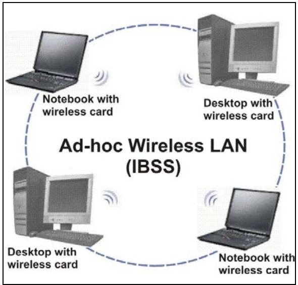
flowchart
graph TD
    A["Laptop"] -->|Notebook with wireless card| B["Desktop with wireless card"]
    B -->|Notebook with wireless card| C["Desktop with wireless card"]
    C -->|Notebook with wireless card| D["Laptop"]
    D -->|Notebook with wireless card| E["Desktop with wireless card"]
    E -->|Notebook with wireless card| F["Laptop"]
    F -->|Notebook with wireless card| G["Desktop with wireless card"]
    G -->|Notebook with wireless card| H["Laptop"]
    H -->|Notebook with wireless card| I["Desktop with wireless card"]
    I -->|Notebook with wireless card| J["Laptop"]
    J -->|Notebook with wireless card| K["Desktop with wireless card"]
    K -->|Notebook with wireless card| L["Laptop"]
    L -->|Notebook with wireless card| M["Desktop with wireless card"]
    M -->|Notebook with wireless card| N["Laptop"]
    N -->|Notebook with wireless card| O["Desktop with wireless card"]
    O -->|Notebook with wireless card| P["Laptop"]
    P -->|Notebook with wireless card| Q["Desktop with wireless card"]
    Q -->|Notebook with wireless card| R["Laptop"]
    R -->|Notebook with wireless card| S["Desktop with wireless card"]
    S -->|Notebook with wireless card| T["Laptop"]
    T -->|Notebook with wireless card| U["Desktop with wireless card"]
    U -->|Notebook with wireless card| V["Laptop"]
    V -->|Notebook with wireless card| W["Desktop with wireless card"]
    W -->|Notebook with wireless card| X["Laptop"]
    X -->|Notebook with wireless card| Y["Desktop with wireless card"]
    Y -->|Notebook with wireless card| Z["Laptop"]
    Z -->|Notebook with wireless card| AA["Desktop with wireless card"]
    AA -->|Notebook with wireless card| AB["Laptop"]
    AB -->|Notebook with wireless card| AC["Desktop with wireless card"]
    AC -->|Notebook with wireless card| AD["Laptop"]
    AD -->|Notebook with wireless card| AE["Desktop with wireless card"]
    AE -->|Notebook with wireless card| AF["Laptop"]
    AF -->|Notebook with wireless card| AG["Desktop with wireless card"]
    AG -->|Notebook with wireless card| AH["Laptop"]
    AH -->|Notebook with wireless card| AI["Desktop with wireless card"]
    AI -->|Notebook with wireless card| AJ["Laptop"]
    AJ -->|Notebook with wireless card| AK["Desktop with wireless card"]
    AK -->|Notebook with wireless card| AL["Laptop"]
    AL -->|Notebook with wireless card| AM["Desktop with wireless card"]
    AM -->|Notebook with wireless card| AN["Laptop"]
    AN -->|Notebook with wireless card| AO["Desktop with wireless card"]
    AO -->|Notebook with wireless card| AP["Laptop"]
    AP -->|Notebook with wireless card| AQ["Desktop with wireless card"]
    AQ -->|Notebook with wireless card| AR["Laptop"]
    AR -->|Notebook with wireless card| AS["Desktop with wireless card"]
    AS -->|Notebook with wireless card| AT["Laptop"]
    AT -->|Notebook with wireless card| AU["Desktop with wireless card"]
    AU -->|Notebook with wireless card| AV["Laptop"]
    AV -->|Notebook with wireless card| AW["Desktop with wireless card"]
    AW -->|Notebook with wireless card| AX["Laptop"]
    AX -->|Notebook with wireless card| AY["Desktop with wireless card"]
    AY -->|Notebook with wireless card| AZ["Laptop"]
    AZ -->|Notebook with wireless card| BA["Desktop with wireless card"]
    BA -->|Notebook with wireless card| BB["Laptop"]
    BB -->|Notebook with wireless card| BC["Desktop with wireless card"]
    BC -->|Notebook with wireless card| BD["Laptop"]
    BD -->|Notebook with wireless card| BE["Desktop with wireless card"]
    BE -->|Notebook with wireless card| BF["Laptop"]
    BF -->|Notebook with wireless card| BG["Desktop with wireless card"]
    BG -->|Notebook with wireless card| BH["Laptop"]
    BH -->|Notebook with wireless card| BI["Desktop with wireless card"]
    BI -->|Notebook with wireless card| BJ["Laptop"]
    BJ -->|Notebook with wireless card| BK["Desktop with wireless card"]
    BK -->|Notebook with wireless card| BL["Laptop"]
    BL -->|Notebook with wireless card| BM["Desktop with wireless card"]
    BM -->|Notebook with wireless card| BN["Laptop"]
    BN -->|Notebook with wireless card| BO["Desktop with wireless card"]
    BO -->|Notebook with wireless card| BP["Laptop"]
    BP -->|Notebook with wireless card| BQ["Desktop with wireless card"]
    BQ -->|Notebook with wireless card| BR["Laptop"]
    BR -->|Notebook with wireless card| BS["Desktop with wireless card"]
    BS -->|Notebook with wireless card| BT["Laptop"]
    BT -->|Notebook with wireless card| BU["Desktop with wireless card"]
    BU -->|Notebook with wireless card| BV["Laptop"]
    BV -->|Notebook with wireless card|
    BV -->|Notebook with wireless card|
Diagram C-1 Peer-to-Peer Communication in an Ad-hoc Network
Infrastructure Wireless LAN Configuration
For Infrastructure WLANs, multiple access points (APs) link the WLAN to the wired network and allow users to efficiently share network resources. The Access Points not only provide communication with the wired network but also mediate wireless network traffic in the immediate neighborhood. Multiple access points can provide wireless coverage for an entire building or campus. All communications between stations or between a station and a wired network client go through the access point.
The Extended Service Set (ESS) shown in the next figure consists of a series of overlapping BSSs (each containing an access point) connected together by means of a Distribution System (DS). Although the DS could be any type of network, it is almost invariably an Ethernet LAN. Mobile nodes can roam between access points and seamless campus-wide coverage is possible.
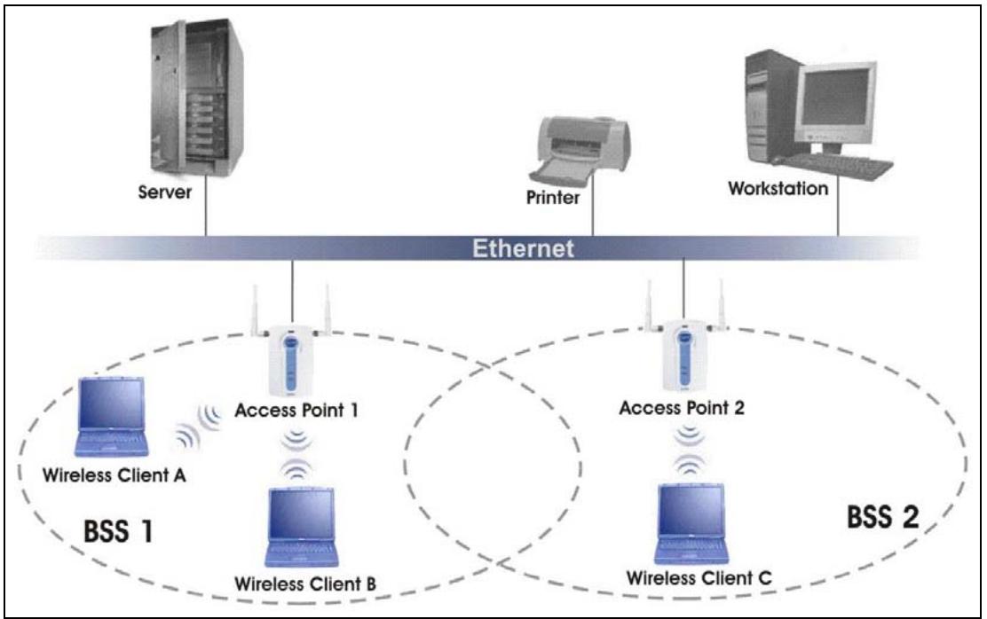
flowchart
graph TD
    Server["Server"] -->|Ethernet| Internet1["Access Point 1"]
    Internet1 -->|BSS 1| WirelessClientA["Wireless Client A"]
    Internet1 -->|BSS 1| WirelessClientB["Wireless Client B"]
    Internet1 -->|BSS 1| WirelessClientC["Wireless Client C"]
    Internet2["Printer"] -->|Ethernet| Internet2["Access Point 2"]
    Internet2 -->|BSS 2| WirelessClientC
    Internet2 -->|BSS 2| WirelessClientB
    Internet2 -->|BSS 2| WirelessClientC
    Workstation["Workstation"] -->|Ethernet| Internet2
    Workstation -->|BSS 2| WirelessClientC
Diagram C-2 ESS Provides Campus-Wide Coverage
Appendix D PPPoE
PPPoE in Action
An ADSL modem bridges a PPP session over Ethernet (PPP over Ethernet, RFC 2516) from your PC to an ATM PVC (Permanent Virtual Circuit) which connects to a xDSL Access Concentrator where the PPP session terminates (see the next figure). One PVC can support any number of PPP sessions from your LAN. PPPoE provides access control and billing functionality in a manner similar to dial-up services using PPP.
Benefits of PPPoE
PPPoE offers the following benefits:
- It provides you with a familiar dial-up networking (DUN) user interface.
- It lessens the burden on the carriers of provisioning virtual circuits all the way to the ISP on multiple switches for thousands of users. For GSTN (PSTN and ISDN), the switching fabric is already in place.
- It allows the ISP to use the existing dial-up model to authenticate and (optionally) to provide differentiated services.
Traditional Dial-up Scenario
The following diagram depicts a typical hardware configuration where the PCs use traditional dial-up networking.
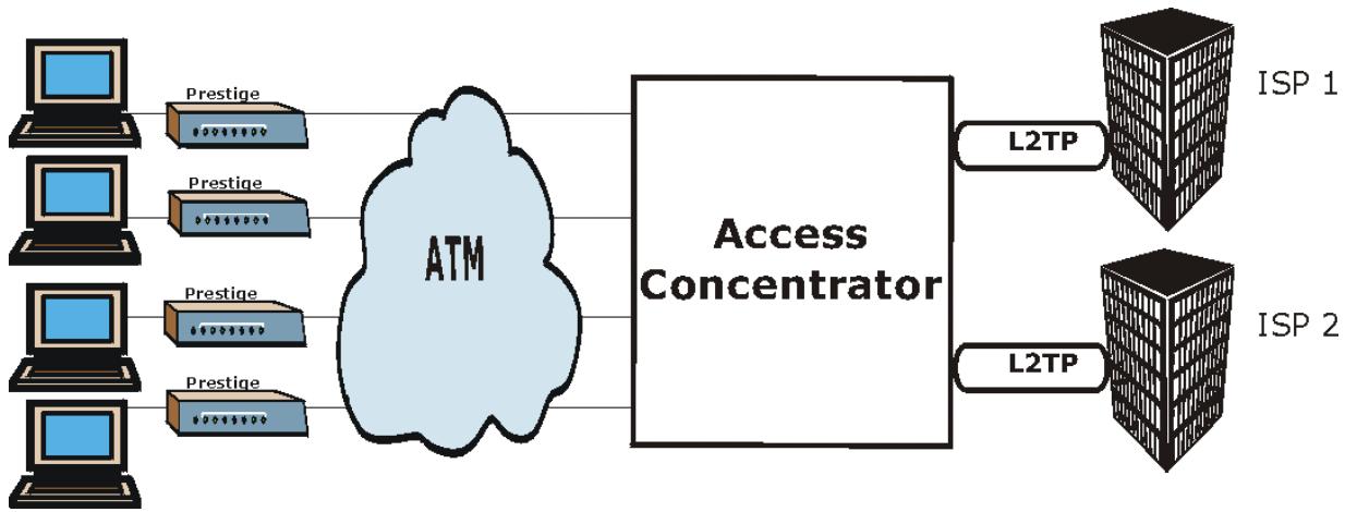
flowchart
graph LR
    A["Computer"] --> B["Prestige"]
    C["Computer"] --> D["Prestige"]
    E["Computer"] --> F["Prestige"]
    G["Computer"] --> H["Prestige"]
    B --> I["ATM"]
    D --> I
    F --> I
    H --> I
    I --> J["Access Concentrator"]
    J --> K["L2TP"]
    J --> L["L2TP"]
    K --> M["ISP 1"]
    L --> N["ISP 2"]
Diagram D-1 Single-PC per Router Hardware Configuration
How PPPoE Works
The PPPoE driver makes the Ethernet appear as a serial link to the PC and the PC runs PPP over it, while the modem bridges the Ethernet frames to the Access Concentrator (AC). Between the AC and an ISP, the AC is acting as a L2TP (Layer 2 Tunneling Protocol) LAC (L2TP Access Concentrator) and tunnels the PPP frames to the ISP. The L2TP tunnel is capable of carrying multiple PPP sessions.
With PPPoE, the VC (Virtual Circuit) is equivalent to the dial-up connection and is between the modem and the AC, as opposed to all the way to the ISP. However, the PPP negotiation is between the PC and the ISP.
Prestige as a PPPoE Client
When using the Prestige as a PPPoE client, the PCs on the LAN see only Ethernet and are not aware of PPPoE. This alleviates the administrator from having to manage the PPPoE clients on the individual PCs.
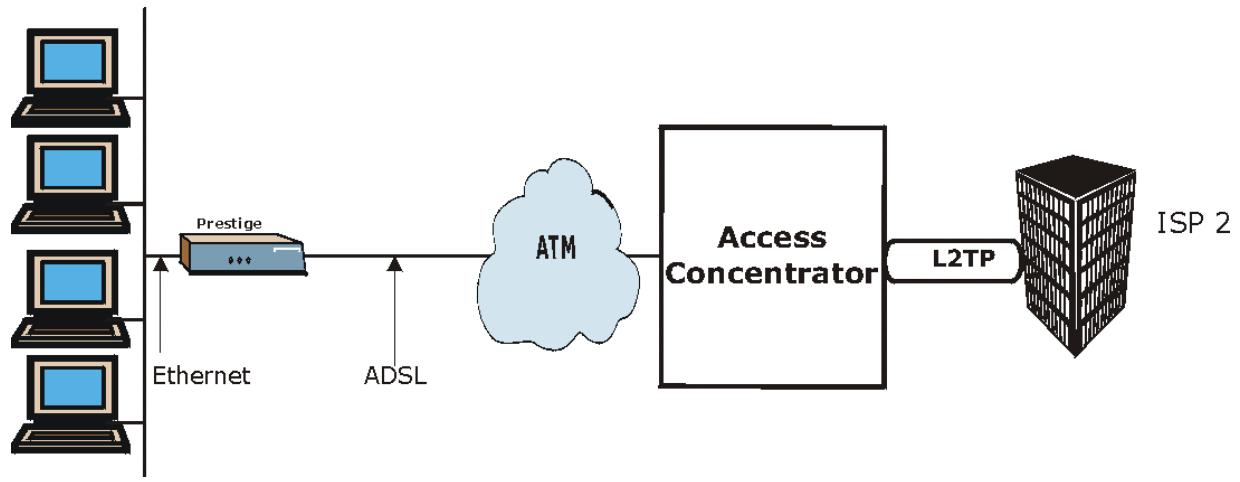
flowchart
graph LR
    A["Computer"] --> B["Prestige"]
    B --> C["ATM"]
    C --> D["Access Concentrator"]
    D --> E["L2TP"]
    E --> F["ISP 2"]
    G["Ethernet"] --> B
    H["ADSL"] --> C
Diagram D-2 Prestige as a PPPoE Client
Appendix E
Virtual Circuit Topology
ATM is a connection-oriented technology, meaning that it sets up virtual circuits over which end systems communicate. The terminology for virtual circuits is as follows:
- Virtual Channel Logical connections between ATM switches
- Virtual Path A bundle of virtual channels
● Virtual Circuit A series of virtual paths between circuit end points virtual circuit
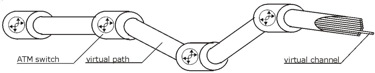
text_image
ATM switch virtual path virtual channelDiagram E-1 Virtual Circuit Topology
Think of a virtual path as a cable that contains a bundle of wires. The cable connects two points and wires within the cable provide individual circuits between the two points. In an ATM cell header, a VPI (Virtual Path Identifier) identifies a link formed by a virtual path; a VCI (Virtual Channel Identifier) identifies a channel within a virtual path.
The VPI and VCI identify a virtual path, that is, termination points between ATM switches. A series of virtual paths make up a virtual circuit.
Your service provider should supply you with VPI/VCI numbers.
Appendix F Setting up Your Computer's IP Address
All computers must have a 10M or 100M Ethernet adapter card and TCP/IP installed.
Windows 95/98/Me/NT/2000/XP, Macintosh OS 7 and later operating systems and all versions of UNIX/LINUX include the software components you need to install and use TCP/IP on your computer. Windows 3.1 requires the purchase of a third-party TCP/IP application package.
TCP/IP should already be installed on computers using Windows NT/2000/XP, Macintosh OS 7 and later operating systems.
After the appropriate TCP/IP components are installed, configure the TCP/IP settings in order to "communicate" with your network.
If you manually assign IP information instead of using dynamic assignment, make sure that your computers have IP addresses that place them in the same subnet as the Prestige's LAN port.
Windows 95/98/Me
Click Start, Settings, Control Panel and double-click the Network icon to open the Network window.
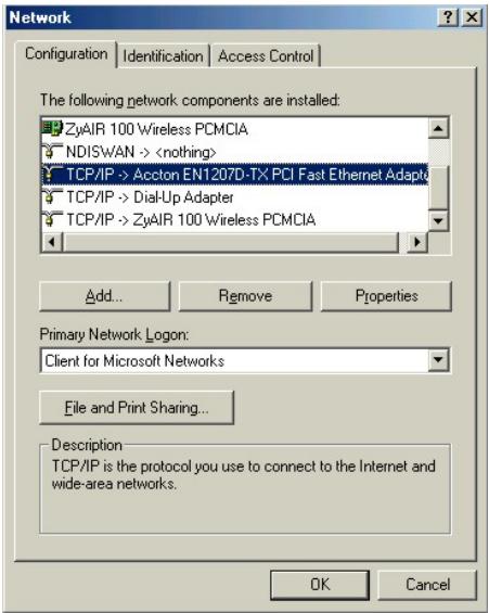
text_image
Network Configuration Identification Access Control The following network components are installed: ZyAIR 100 Wireless PCMCIA NDISWAN ->Installing Components
The Network window Configuration tab displays a list of installed components. You need a network adapter, the TCP/IP protocol and Client for Microsoft Networks.
If you need the adapter:
a. In the Network window, click Add.
b. Select Adapter and then click Add.
c. Select the manufacturer and model of your network adapter and then click OK.
If you need TCP/IP:
a. In the Network window, click Add.
b. Select Protocol and then click Add.
c. Select Microsoft from the list of manufacturers.
d. Select TCP/IP from the list of network protocols and then click OK.
If you need Client for Microsoft Networks:
a. Click Add.
b. Select Client and then click Add.
c. Select Microsoft from the list of manufacturers.
d. Select Client for Microsoft Networks from the list of network clients and then click OK.
e. Restart your computer so the changes you made take effect.
Configuring
- In the Network window Configuration tab, select your network adapter's TCP/IP entry and click Properties.
2. Click the IP Address tab.
-If your IP address is dynamic, select Obtain an IP address automatically.
-If you have a static IP address, select Specify an IP address and type your information into the IP Address and Subnet Mask fields.
3. Click the DNS Configuration tab.
-If you do not know your DNS information, select Disable DNS.
-If you know your DNS information, select Enable DNS and type the information in the fields below (you may not need to fill them all in).
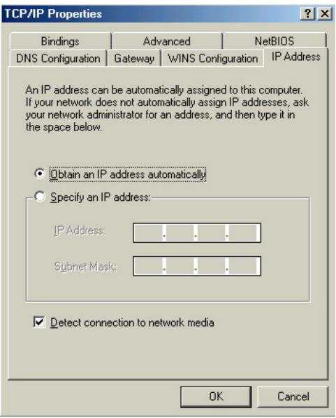
text_image
TCP/IP Properties Bindings Advanced NetBIOS DNS Configuration Gateway WINS Configuration IP Address An IP address can be automatically assigned to this computer. If your network does not automatically assign IP addresses, ask your network administrator for an address, and then type it in the space below. Obtain an IP address automatically Specify an IP address: IP Address: . Subnet Mask: . Detect connection to network media OK Cancel
text_image
TCP/IP Properties Bindings Advanced NetsBIOS DNS Configuration Gateway WINS Configuration IP Address Disable DNS Enable DNS Host: Domain: DNS Server Search Order Add Remove Domain Suffix Search Order Add Remove OK Cancel- Click the Gateway tab.
-If you do not know your gateway's IP address, remove previously installed gateways.
-If you have a gateway IP address, type it in the New gateway field and click Add.
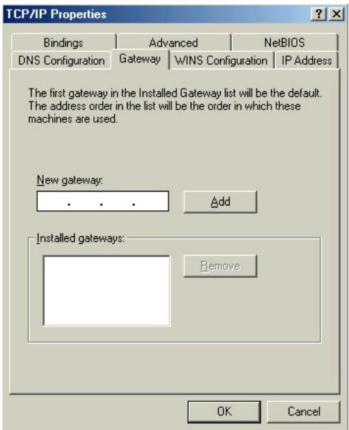
text_image
TCP/IP Properties Bindings Advanced NetsBIOS DNS Configuration Gateway WINS Configuration IP Address The first gateway in the Installed Gateway list will be the default. The address order in the list will be the order in which these machines are used. New gateway: . . . Add Installed gateways: Remove OK Cancel- Click OK to save and close the TCP/IP Properties window.
- Click OK to close the Network window. Insert the Windows CD if prompted.
- Turn on your Prestige and restart your computer when prompted.
Verifying Settings
-
Click Start and then Run.
-
In the Run window, type "winipcfg" and then click OK to open the IP Configuration window.
-
Select your network adapter. You should see your computer's IP address, subnet mask and default gateway.
Windows 2000/NT/XP
- For Windows XP, click start, Control Panel. In Windows 2000/NT, click Start, Settings, Control Panel.
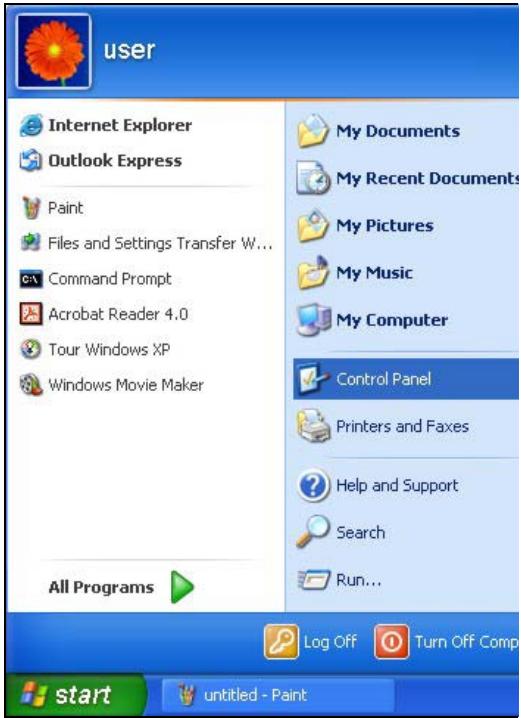
text_image
user Internet Explorer Outlook Express Paint Files and Settings Transfer W... Command Prompt Acrobat Reader 4.0 Tour Windows XP Windows Movie Maker All Programs My Documents My Recent Documents My Pictures My Music My Computer Control Panel Printers and Faxes Help and Support Search Run... Log Off Turn Off Comp start untitled - Paint- For Windows XP, click Network Connections. For Windows 2000/NT, click Network and Dial-up Connections.
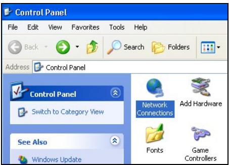
text_image
Control Panel File Edit View Favorites Tools Help Back Search Folders Address Control Panel Control Panel Switch to Category View Network Connections Add Hardware Se Aso Fonts Game Windows Update Controllers- Right-click Local Area Connection and then click Properties.
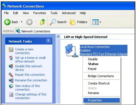
text_image
Network Connections File Edit View Favorites Tools Advanced Help Back Search Folders Address Network Connections Network Tasks LAN or High-Speed Internet Create a new connection Set up a home or small office network Disable this network device Repair this connection Rename this connection View status of this connection Change settings of this connection Local Area Connection Enabled Standard PCI Fast Ethernet Adapter Disable Status Repair Bridge Connections Create Shortcut Delete Rename Properties-
Select Internet Protocol (TCP/IP) (under the General tab in Win XP) and click Properties.
-
The Internet Protocol TCP/IP Properties window opens (the General tab in Windows XP).
-If you have a dynamic IP address click Obtain an IP address automatically.
-If you have a static IP address click Use the following IP Address and fill in the IP address, Subnet mask, and Default gateway fields.
Click Advanced.
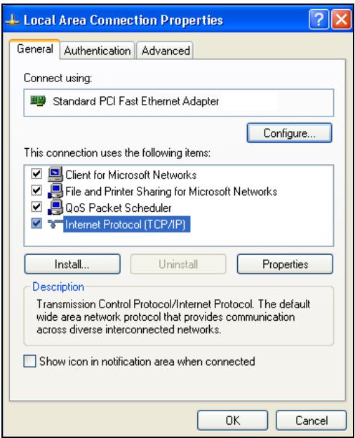
text_image
Local Area Connection Properties General Authentication Advanced Connect using: Standard PCI Fast Ethernet Adapter Configure... This connection uses the following items: Client for Microsoft Networks File and Printer Sharing for Microsoft Networks QoS Packet Scheduler Internet Protocol (TCP/IP) Install... Uninstall Properties Description Transmission Control Protocol/Internet Protocol. The default wide area network protocol that provides communication across diverse interconnected networks. Show icon in notification area when connected OK Cancel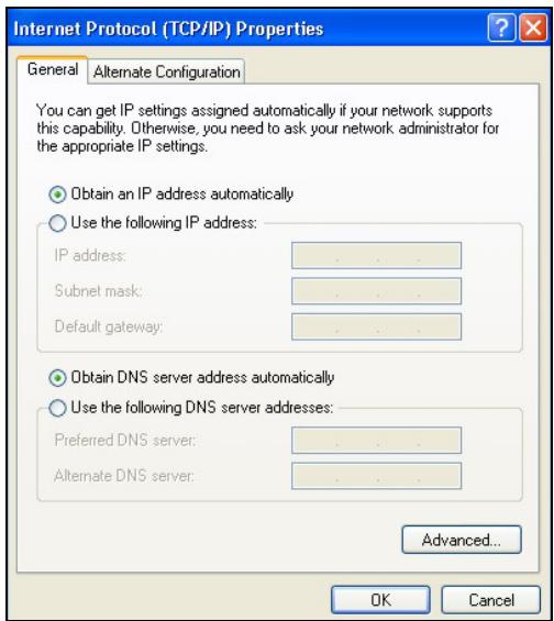
text_image
Internet Protocol (TCP/IP) Properties General Alternate Configuration You can get IP settings assigned automatically if your network supports this capability. Otherwise, you need to ask your network administrator for the appropriate IP settings. Obtain an IP address automatically Use the following IP address: IP address: .. Subnet mask: .. Default gateway: .. Obtain DNS server address automatically Use the following DNS server addresses: Preferred DNS server: .. Alternate DNS server: .. Advanced... OK Cancel- -If you do not know your gateway's IP address, remove any previously installed gateways in the IP Settings tab and click OK.
Do one or more of the following if you want to configure additional IP addresses:
-In the IP Settings tab, in IP addresses, click Add.
-In TCP/IP Address, type an IP address in IP address and a subnet mask in Subnet mask, and then click Add.
-Repeat the above two steps for each IP address you want to add.
-Configure additional default gateways in the IP Settings tab by clicking Add in Default gateways.
-In TCP/IP Gateway Address, type the IP address of the default gateway in Gateway. To manually configure a default metric (the number of transmission hops), clear the Automatic metric check box and type a metric in Metric.
-Click Add.
-Repeat the previous three steps for each default gateway you want to add.
-Click OK when finished.
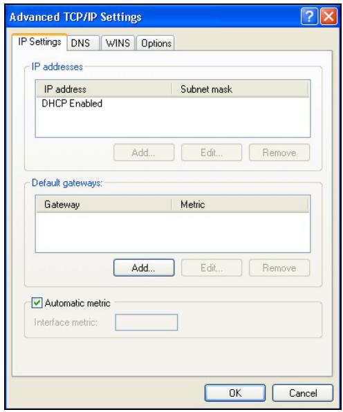
text_image
Advanced TCP/IP Settings IP Settings DNS WINS Options IP addresses IP address Subnet mask DHCP Enabled Add... Edit... Remove Default gateways: Gateway Metric Add... Edit... Remove Automatic metric Interface metric: OK Cancel- In the Internet Protocol TCP/IP Properties window (the General tab in Windows XP):
-Click Obtain DNS server address automatically if you do not know your DNS server IP address(es).
-If you know your DNS server IP address(es), click Use the following DNS server addresses, and type them in the Preferred DNS server and Alternate DNS server fields.
If you have previously configured DNS servers, click Advanced and then the DNS tab to order them.
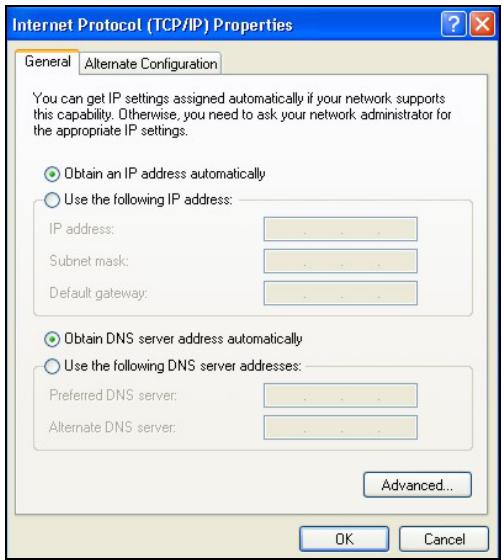
text_image
Internet Protocol (TCP/IP) Properties General Alternate Configuration You can get IP settings assigned automatically if your network supports this capability. Otherwise, you need to ask your network administrator for the appropriate IP settings. Obtain an IP address automatically Use the following IP address: IP address: .. Subnet mask: .. Default gateway: .. Obtain DNS server address automatically Use the following DNS server addresses: Preferred DNS server: .. Alternate DNS server: .. Advanced... OK Cancel- Click OK to close the Internet Protocol (TCP/IP) Properties window.
- Click OK to close the Local Area Connection Properties window.
- Turn on your Prestige and restart your computer (if prompted).
Verifying Settings
- Click Start, All Programs, Accessories and then Command Prompt.
- In the Command Prompt window, type "ipconfig" and then press [ENTER]. You can also open Network Connections, right-click a network connection, click Status and then click the Support tab.
Macintosh OS 8/9
- Click the Apple menu, Control Panel and double-click TCP/IP to open the TCP/IP Control Panel.
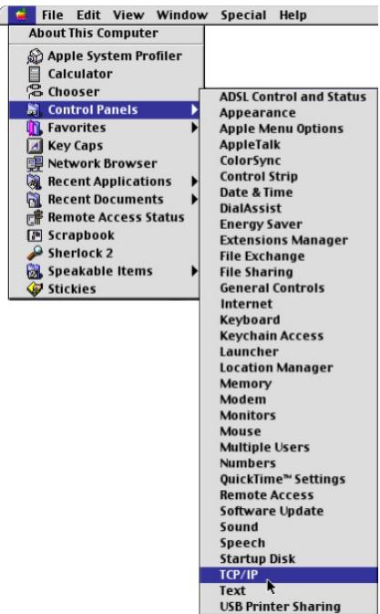
text_image
File Edit View Window Special Help About This Computer Apple System Profiler Calculator Chooser Control Panels Favorites Key Caps Network Browser Recent Applications Recent Documents Remote Access Status Scrapbook Sherlock 2 Speakable Items Stickies ADSL Control and Status Appearance Apple Menu Options AppleTalk ColorSync Control Strip Date & Time DialAssist Energy Saver Extensions Manager File Exchange File Sharing General Controls Internet Keyboard Keychain Access Launcher Location Manager Memory Modem Monitors Mouse Multiple Users Numbers QuickTime™ Settings Remote Access Software Update Sound Speech Startup Disk TCP/IP Text USB Printer Sharing- Select Ethernet built-in from the Connect via list.
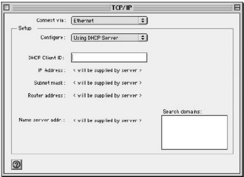
text_image
TCP/IP Connect via: Ethernet Setup Configure: Using DHCP Server DHCP Client ID: IP Address: < will be supplied by server > Subnet mask: < will be supplied by server > Router address: < will be supplied by server > Name server addr.: < will be supplied by server > Search domains:- For dynamically assigned settings, select Using DHCP Server from the Configure: list.
- For statically assigned settings, do the following:
-From the Configure box, select Manually.
-Type your IP address in the IP Address box.
-Type your subnet mask in the Subnet mask box.
-Type the IP address of your Prestige in the Router address box.
- Close the TCP/IP Control Panel.
- Click Save if prompted, to save changes to your configuration.
- Turn on your Prestige and restart your computer (if prompted).
Verifying Settings
Check your TCP/IP properties in the TCP/IP Control Panel window.
Macintosh OS X
- Click the Apple menu, and click System Preferences to open the System Preferences window.
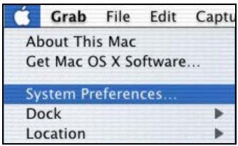
text_image
Grab File Edit Captu About This Mac Get Mac OS X Software... System Preferences... Dock Location-
Click Network in the icon bar.
-
Select Automatic from the Location list.
- Select Built-in Ethernet from the Show list.
- Click the TCP/IP tab.
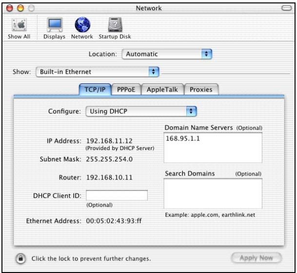
text_image
Network Show All Displays Network Startup Disk Location:Automatic Show:Built-in Ethernet TCP/IP PPPoE AppleTalk Proxies Configure:Using DHCP IP Address:192.168.11.12 (Provided by DHCP Server) Subnet Mask:255.255.254.0 Router:192.168.10.11 DHCP Client ID: (Optional) Ethernet Address:00:05:02:43:93.ff Domain Name Servers (Optional) 168.95.1.1 Search Domains (Optional) Example: apple.com, earthlink.net Click the lock to prevent further changes. Apply Now- For dynamically assigned settings, select Using DHCP from the Configure list.
- For statically assigned settings, do the following:
-From the Configure box, select Manually.
-Type your IP address in the IP Address box.
-Type your subnet mask in the Subnet mask box.
-Type the IP address of your Prestige in the Router address box.
- Click Apply Now and close the window.
- Turn on your Prestige and restart your computer (if prompted).
Verifying Settings
Check your TCP/IP properties in the Network window.
Appendix G
Splitters and Microfilters
This appendix tells you how to install a POTS splitter or a telephone microfilter.
Connecting a POTS Splitter
When you use the Full Rate (G.dmt) ADSL standard, you can use a POTS (Plain Old Telephone Service) splitter to separate the telephone and ADSL signals. This allows simultaneous Internet access and telephone service on the same line. A splitter also eliminates the destructive interference conditions caused by telephone sets.
Install the POTS splitter at the point where the telephone line enters your residence, as shown in the following figure.
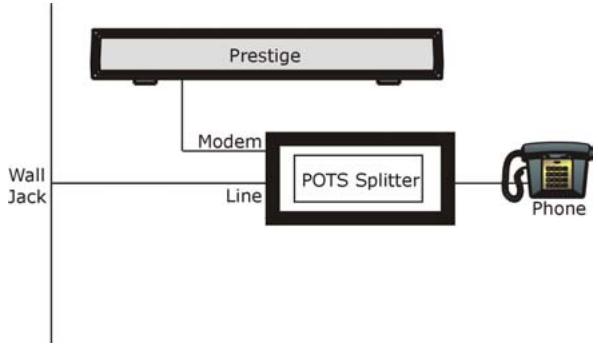
flowchart
graph TD
    A["Prestige"] --> B["Modem"]
    B --> C["POTS Splitter"]
    C --> D["Phone"]
    style A fill:#f9f,stroke:#333
    style B fill:#ccf,stroke:#333
    style C fill:#cfc,stroke:#333
    style D fill:#fcc,stroke:#333
Diagram G-1 Connecting a POTS Splitter
Step 1. Connect the side labeled “Phone” to your telephone.
Step 2. Connect the side labeled “Modem” to your Prestige.
Step 3. Connect the side labeled "Line" to the telephone wall jack.
Telephone Microfilters
Telephone voice transmissions take place in the lower frequency range, 0 - 4KHz, while ADSL transmissions take place in the higher bandwidth range, above 4KHz. A microfilter acts as a low-pass filter, for your telephone, to ensure that ADSL transmissions do not interfere with your telephone voice transmissions. The use of a telephone microfilter is optional.
Step 1. Connect a phone cable from the wall jack to the single jack end of the Y- Connector.
Step 2. Connect a cable from the double jack end of the Y-Connector to the “wall side” of the microfilter.
Step 3. Connect another cable from the double jack end of the Y-Connector to the Prestige.
Step 4. Connect the “phone side” of the microfilter to your telephone as shown in the following figure.
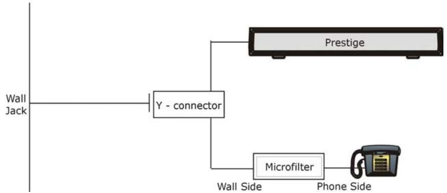
flowchart
graph TD
    A["Wall Jack"] --> B["Y - connector"]
    B --> C["Prestige"]
    B --> D["Microfilter"]
    D --> E["Phone Side"]
Diagram G-2 Connecting a Microfilter
Prestige With ISDN
This section relates to people who use their Prestige with ADSL over ISDN (digital telephone service) only. The following is an example installation for the Prestige with ISDN.
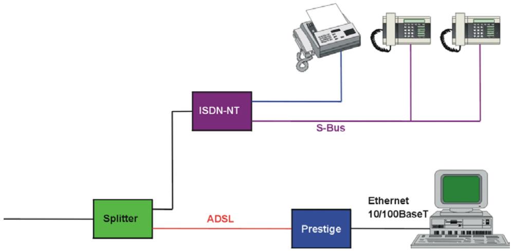
flowchart
graph LR
    A["Splitter"] -->|ADSL| B["ISDN-NT"]
    B -->|S-Bus| C["Ethernet 10/100BaseT"]
    B --> D["Prestige"]
    D -->|ADSL| A
Diagram G-3 Prestige with ISDN
Appendix H
Power Adaptor Specifications
H.1 Prestige 650R-E1/-E3/-E7 ADSL Router
| NORTH AMERICA PLUG STANDARDS | |
| AC Power Adapter model | DV-121AACS |
| Input power | AC120Volts/60Hz/23W max. |
| Output power | AC12Volts/1.0A |
| Power consumption | 8 W |
| Safety standards | UL, CUL (UL 1310, CSA C22.2 No.223) |
| NORTH AMERICA PLUG STANDARDS | |
| AC Power Adapter model | AA-121A |
| Input power | AC120Volts/60Hz/18W max. |
| Output power | AC12Volts/1.0A |
| Power consumption | 8 W |
| Safety standards | UL, CUL (UL 1310, CSA C22.2 No.223) |
| CHINESE PLUG STANDARDS | |
| AC Power Adapter model | DV-121AACCP-5720 |
| Input power | AC220Volts/50Hz/18W |
| Output power | AC12Volts/1.0A |
| Power consumption | 8 W |
| Safety standards | CCEE (GB8898) |
| CHINESE PLUG STANDARDS | |
| AC Power Adapter model | BH-48 (AA-121AP) |
| Input power | AC220Volts/50Hz |
| Output power | AC12Volts/1.0A |
| Power consumption | 8 W |
| Safety standards | CCEE (GB8898) |
| EUROPEAN PLUG STANDARDS | |
| AC Power Adapter model | DV-121AACCP-5716 |
| Input power | AC230Volts/50Hz/100mA |
| Output power | AC12Volts/1.0A |
| Power consumption | 8 W |
| Safety standards | TUV-GS, CE (EN 60950) |
| EUROPEAN PLUG STANDARDS | |
| AC Power Adapter model | AA-121ABN |
| Input power | AC230Volts/50Hz/140mA |
| Output power | AC12Volts/1.0A |
| Power consumption | 8 W |
| Safety standards | ITS-GS, CE (EN 60950) |
| UNITED KINGDOM PLUG STANDARDS | |
| AC Power Adapter model | AA-121AD |
| Input power | AC230Volts/50Hz/140mA |
| Output power | AC12Volts/1.0A |
| Power consumption | 8 W |
| Safety standards | ITS-GS, CE (EN 60950, BS 7002) |
H.2 Prestige 650R-11 ADSL Router
| NORTH AMERICA PLUG STANDARDS | |
| AC Power Adapter model | DV-121AACS |
| Input power | AC120Volts/60Hz/23W |
| Output power | AC12Volts/1.0A |
| Power consumption | 10 W |
| Safety standards | UL, CUL (UL 1310, CSA C22.2 No.223) |
| CHINESE PLUG STANDARDS | |
| AC Power Adapter model | DV-121AACCP-5720 |
| Input power | AC220Volts/50Hz/18W |
| Output power | AC12Volts/1.0A |
| Power consumption | 10 W |
| Safety standards | CCEE (GB8898) |
| EUROPEAN PLUG STANDARDS | |
| AC Power Adapter model | DV-121AACUP-5716 |
| Input power | AC230Volts/50Hz/19W |
| Output power | AC12Volts/1.0A |
| Power consumption | 10W |
| Safety standards | TUV, CE (EN 61558) |
H.3 Prestige 650R-13/-17 ADSL Ethernet Router
| NORTH AMERICA PLUG STANDARDS | |
| AC Power Adapter model | DV-121AACS |
| Input power | AC120Volts/60Hz/23W max. |
| Output power | AC12Volts/1.0A |
| Power consumption | 12 W |
| Safety standards | UL, CUL (UL 1310, CSA C22.2 No.223) |
| NORTH AMERICA PLUG STANDARDS | |
| AC Power Adapter model | AA-121A |
| Input power | AC120Volts/60Hz/18W max. |
| Output power | AC12Volts/1.0A |
| Power consumption | 12 W |
| Safety standards | UL, CUL (UL 1310, CSA C22.2 No.223) |
| CHINESE PLUG STANDARDS | |
| AC Power Adapter model | DV-121AACCP-5720 |
| Input power | AC220Volts/50Hz/18W |
| Output power | AC12Volts/1.0A |
| Power consumption | 12 W |
| Safety standards | CCEE (GB8898) |
| EUROPEAN PLUG STANDARDS | |
| AC Power Adapter model | AA-121ABN |
| Input power | AC230Volts/50Hz/140mA |
| Output power | AC12Volts/1.0A |
| Power consumption | 12 W |
| Safety standards | ITS-GS, CE (EN 60950) |
H.4 Prestige 650R-31/-33 ADSL over ISDN Router
| NORTH AMERICA PLUG STANDARDS | |
| AC Power Adapter model | DV-121AACS |
| Input power | AC120Volts/60Hz/23W max. |
| Output power | AC12Volts/1.0A |
| Power consumption | 8 W |
| Safety standards | UL, CUL (UL 1310, CSA C22.2 No.223) |
| NORTH AMERICA PLUG STANDARDS | |
| AC Power Adapter model | AA-121A |
| Input power | AC120Volts/60Hz/18W max. |
| Output power | AC12Volts/1.0A |
| Power consumption | 8 W |
| Safety standards | UL, CUL (UL 1310, CSA C22.2 No.223) |
| CHINESE PLUG STANDARDS | |
| AC Power Adapter model | DV-121AACCP-5720 |
| Input power | AC220Volts/50Hz/18W |
| Output power | AC12Volts/1.0A |
| Power consumption | 8 W |
| Safety standards | CCEE (GB8898) |
| EUROPEAN PLUG STANDARDS | |
| AC Power Adapter model | AA-121ABN |
| Input power | AC230Volts/50Hz/140mA |
| Output power | AC12Volts/1.0A |
| Power consumption | 8 W |
| Safety standards | ITS-GS, CE (EN 60950) |
| EUROPEAN PLUG STANDARDS | |
| AC Power Adapter model | DV-121AACCP-5716 |
| Input power | AC230Volts/50Hz/100mA |
| Output power | AC12Volts/1.0A |
| Power consumption | 8 W |
| Safety standards | TUV-GS, CE (EN 60950) |
| UNITED KINGDOM PLUG STANDARDS | |
| AC Power Adapter model | AA-121AD |
| Input power | AC230Volts/50Hz/140mA |
| Output power | AC12Volts/1.0A |
| Power consumption | 8 W |
| Safety standards | ITS-GS, CE (EN 60950) |
H.5 Prestige 650H-11/-13 ADSL Router with 4-Port Ethernet Switch
| NORTH AMERICA PLUG STANDARDS | |
| AC Power Adapter model | DV-1215A |
| Input power | AC120Volts/60Hz/30W |
| Output power | AC 12Volts/ 1.25A |
| Power consumption | 12 W |
| Safety standards | UL, CUL, CSA (UL 1310, CSA C22.2 No.223) |
| NORTH AMERICA PLUG STANDARDS | |
| AC Power Adapter model | AA-121A25 |
| Input power | AC120Volts/60Hz/19W |
| Output power | AC 12Volts/ 1.25A |
| Power consumption | 12 W |
| Safety standards | UL, CUL (UL 1310, CSA C22.2 No.223) |
| EUROPEAN PLUG STANDARDS | |
| AC Power Adapter model | AA-121A3BN |
| Input power | AC230Volts/50Hz/140mA |
| Output power | AC12Volts/1.3A |
| Power consumption | 12 W |
| Safety standards | ITS-GS, CE (EN 60950) |
H.6 Prestige 650HW-11/-13 ADSL Router with 4-Port Ethernet Switch/Wireless LAN
| NORTH AMERICA PLUG STANDARDS | |
| AC Power Adapter model | DV-1215A |
| Input power | AC120Volts/60Hz/30W |
| Output power | AC 12Volts/ 1.25A |
| Power consumption | 13 W |
| Safety standards | UL, CUL, CSA (UL 1310, CSA C22.2 No.223) |
| NORTH AMERICA PLUG STANDARDS | |
| AC Power Adapter model | AA-121A25 |
| Input power | AC120Volts/60Hz/19W |
| Output power | AC 12Volts/ 1.25A |
| Power consumption | 13 W |
| Safety standards | UL, CUL (UL 1310, CSA C22.2 No.223) |
| EUROPEAN PLUG STANDARDS | |
| AC Power Adapter model | AA-121A3BN |
| Input power | AC230Volts/50Hz/140mA |
| Output power | AC12Volts/1.3A |
| Power consumption | 13 W |
| Safety standards | ITS-GS, CE (EN 60950) |
H.7 Prestige 650HW-31/-33/-37; Prestige 650H-31/-33/-37 ADSL Router with 4-port Switch/Wireless
| NORTH AMERICA PLUG STANDARDS | |
| AC Power Adapter model | DV-1215A |
| Input power | AC120Volts/60Hz/30W |
| Output power | AC 12Volts/ 1.25A |
| Power consumption | 15 W |
| Safety standards | UL, CUL, CSA (UL 1310, CSA C22.2 No.223) |
| NORTH AMERICA PLUG STANDARDS | |
| AC Power Adapter model | AA-121A25 |
| Input power | AC120Volts/60Hz/19W |
| Output power | AC 12Volts/ 1.25A |
| Power consumption | 15 W |
| Safety standards | UL, CUL (UL 1310, CSA C22.2 No.223) |
| EUROPEAN PLUG STANDARDS | |
| AC Power Adapter model | AA-121A3BN |
| Input power | AC230Volts/50Hz/140mA |
| Output power | AC12Volts/1.3A |
| Power consumption | 15 W |
| Safety standards | ITS-GS, CE (EN 60950) |
| UNITED KINGDOM PLUG STANDARDS | |
| AC Power Adapter model | AA-121A3D |
| Input power | AC230Volts/50Hz/140mA |
| Output power | AC12Volts/1.3A |
| Power consumption | 15 W |
| Safety standards | ITS-GS, CE (EN 60950) |
A
Address Assignment 4-2
Ad-hoc Configuration C-2
ADSL, what is it?...... xxiii
Alternative Subnet Mask Notation...... B-3
AT command 27-1
Authentication....19-4, 19-5
auto-negotiation 1-3
B
Backup 27-2
Bandwidth Borrowing.... 12-7
Bandwidth Class 12-1
Bandwidth Filter 12-1, 12-14
Bandwidth Management 12-1
Bandwidth Management Statistics.... 12-15
Bandwidth Manager Class Configuration .... 12-12
Bandwidth Manager Class Setup 12-11
Bandwidth Manager Monitor.... 12-17
Bandwidth Manager Summary 12-9
Basic Service Set.... C-2
Borrow bandwidth from parent class ...... 12-14
Bridging 16-2
Ether Address 21-4
Ethernet....21-1
Ethernet Addr Timeout 21-3
Remote Node 21-1
Static Route Setup.... 21-3
BSS ...... See Basic Service Set
Budget Management 28-2, 28-3
BW Budget.... 12-13
C
Call Filtering 23-1
Appendix I Index
Call Filters
Built-In 23-1
User-Defined 23-1
Call Scheduling.
Maximum Number of Schedule Sets...... 31-1
PPPoE.... 31-3
Precedence.... 31-1
Precedence Example...... See precedence
CDR 26-7
CDR (Call Detail Record).
Channel ID 17-2
CHAP 19-4
Class Name 12-13
Classes of IP Addresses....B-1
Collision.... 26-3
Command Interpreter Mode.... 28-1
Community 24-2
Computer Name.... 15-1
Conditions that prevent TFTP and FTP from working over WAN 27-4
Configuration.... 3-12, 13-6
Copyright......ii
Cost Of Transmission 19-8, 20-3
Country Code.... 26-4
CPU Load 26-3
Customer Support......v
D
Data encryption.... 5-4
Data Filtering 23-1
Device Filter rules.... 23-16
DHCP 1-4,3-12,4-2,8-1,13-6,26-5
Diagnostic Tools 26-1
Digital Subscriber Line Access Multiplexer.... 1-6
Direct Sequence Spread Spectrum......C-1
Distribution System ......C-2
DNS 16-3
Domain Name....4-2, 7-6
Domain Name System 4-1
DS ...... See Distribution System
DSL (Digital Subscriber Line)...... xxiii
DSL, What Is It? ...... xxiii
DSLAM ......See Digital Subscriber Line Access Multiplexer
DSSS......See Direct Sequence Spread Spectrum
Dynamic DNS....1-3, 8-1, 15-2
DYNDNS Wildcard.... 8-1
E
EAP.... 1-3
ECHO 7-6
Encapsulation....1-5, 3-1, 18-5, 19-2
ENET ENCAP 3-1
PPP over Ethernet.... 3-1
PPPoA 3-1
RFC 1483 3-2
Error Log 26-5
Error/Information Messages Sample 26-6
ESS ...... See Extended Service Set
ESS ID 5-1
Ethernet Encapsulation 7-5
Ethernet Traffic 23-20
Extended Service Set ...... C-2
F
Factory LAN Defaults 4-2
Fairness-based Scheduler.... 12-4
FCC....iii
FHSS... See Frequency-Hopping Spread Spectrum
Filename Conventions 27-1
Filter 16-1
Applying Filters.... 23-19
Ethernet traffic.... 23-20
Ethernet Traffic 23-20
Filter Rules 23-8
Filter Structure.... 23-4
Generic Filter Rule....23-14
Remote Node....19-9
Remote Node Filter....19-9
Remote Node Filters 23-20
Sample....23-18
SUA....23-16
TCP/IP Filter Rule....23-9
Filter Log.... 26-7, 26-8
Filter Rule....23-10
Filter Rule Process....23-3
Filter Rule Setup....23-9
Filter Rules Summary Sample....23-19
Filter Set Class....23-9
Filter Set Configuration.... 23-4, 23-6
Filtering 23-1, 23-9
Filtering Process Outgoing Packets ....23-2
Finger 7-6
Firmware File Maintenance....13-12
Forgot My Login Password....A-4
Fragment Threshold....17-2
Fragmentation Threshold....5-3
Frame Relay 1-6
Frequency-Hopping Spread Spectrum...... C-1
FTP ....7-5, 7-6, 8-1, 10-1, 29-2 Restrictions....29-2
FTP File Transfer 27-10
FTP Restrictions 10-1, 27-4
FTP Server....22-15
Full Rate ...... G-1
G
Gateway....20-3
Gateway Node 21-4
General Setup 15-1
H
Hidden Menus 14-4
Hop Count....19-8, 20-3
Host 2-3
Host IDs ...... B-1
HTTP 7-6
HyperTerminal program 27-6, 27-9
I
IANA 3-5
IBSS......See Independent Basic Service Set
IEEE 802.11 C-1
IEEE 802.1x....1-3
IGMP 4-3
IGMP support.... 19-8
Independent Basic Service Set...... C-2
Infrastructure Configuration...... C-2
Install UPnP 11-3
Windows Me....11-3
Windows XP 11-4
Interactive Applications 30-1
Internet access....18-1
Internet Access 1-2, 1-3, 1-6, 1-7, 16-2, 18-1, 18-5
Internet Access Setup....A-5, 22-1
Internet Assigned Numbers Authority .. See IANA
IP Address.... 3-4, 4-3, 7-5, 7-8,
13-6, 16-3, 20-3, 21-4, 23-11, 26-4, 26-9, 30-3
IP Address Assignment 3-4
ENET ENCAP 3-5
PPPoA or PPPoE 3-5
RFC 1483....3-5
IP Addressing...... B-1
IP Alias Setup 18-2
IP Classes.... B-1
IP Filter 23-13
Logic Flow....23-12
IP mask 23-11
IP Packet 23-14
IP Policies 30-5
IP Policy Routing (IPPR)....1-4, 18-1
Applying an IP Policy....30-5
Ethernet IP Policies.... 30-5
Gateway 30-5
IP Pool Setup 3-13
IP Protocol 30-4
IP Routing Policy (IPPR).... 30-1
Benefits.... 30-1
Cost Savings 30-1
Criteria.... 30-1
Load Sharing 30-1
Setup 30-2
IP Routing Policy Setup.... 30-3
IP Static Route 20-1
IP Static Route Setup 20-2
ISDN....G-2
L
LAN 26-3
LAN Setup 4-1, 6-1
LAN TCP/IP 4-2
Link type.... 26-2
LLC-based Multiplexing.... 19-13
Log and Trace 26-6
Log Facility 26-7
Logging Option....23-11, 23-15
Login.... 19-4
M
MAC address 21-4
MAC Address Filter 17-3
MAC Address Filter Action.... 5-9, 17-4
MAC Address Filtering 5-7
Main Menu 14-4
Management Information Base (MIB)...... 24-2
Maximize Bandwidth Usage.... 12-4, 12-11
MBS...... See Maximum Burst Size
Media Access Control.... 21-1
Message Logging 26-5
Metric....19-5, 19-8, 20-3
Multicast 4-3, 19-8
Multiplexing
LLC-based 3-2
VC-based 3-2
Multiplexing 1-5, 3-2, 18-6, 19-2
Multiprotocol Encapsulation.... 3-2
My WAN Address 19-7
N
Nailed-Up Connection 3-6
NAT....3-4, 7-5, 7-7, 23-16
Application 7-3
Applying NAT in the SMT Menus...... 22-1
Configuring 22-3
Definitions 7-1
Examples 22-11
How NAT Works 7-2
Mapping Types.... 7-3
Non NAT Friendly Application Programs22-17
Ordering Rules 22-6
Server Sets 7-5
What NAT does.... 7-1
NAT Traversal.... 11-1
Network Address Translation 18-7
Network Address Translation (NAT) 22-1
Network Management 1-5, 7-6
NNTP 7-6
P
Packet
Error 26-2
Received 26-3
Transmitted.... 26-3
Packet Triggered 26-7
Packets 26-2
PAP 19-4
Password....2-3, 14-1, 14-6, 19-4, 24-2
Ping....26-9
Point-to-Point.... xxiii
Point-to-Point Tunneling Protocol.. 7-6. See PPTP
policy-based routing 30-1
POP3 7-6
Port Numbers 7-6
PPP Encapsulation.... 19-13
PPP Log 26-7, 26-8
PPPoA....19-2
PPTP 7-6
Precedence.... 30-1, 30-4
Priority....12-14
Priority-based Scheduler 12-4
Private.... 19-8, 20-4
Proportional Bandwidth Allocation....12-2
Protocol 23-10
Protocol Filter Rules....23-16
Q
Quality of Service....30-1
Quick Start Guide....2-1
R
RADIUS....1-3
RAS 26-4,30-2
Rate
Receiving 26-2
Transmission 26-2
Read Me First .....xxi
Related Documentation ......xxi
Remote Authentication Dial In User Service ...See RADIUS
Remote DHCP Server....16-3
Remote Management and NAT 10-1
Remote Management Limitations ..... 10-1, 29-2
Remote Management Setup....29-1
Remote Node 19-1, 26-2
Profile (Traffic Redirect Field)....19-15
Remote Node Profile....19-3
Remote Node Setup.... 19-1, 19-2
Remote Node Index Number 26-2
Remote Node Traffic 23-21
Required fields 14-4
Restore Configuration 27-7
RF signals....C-1
RFC-1483 19-2
RFC-2364 19-2, 19-3
RIP. 16-3, 19-8. See Routing Information Protocol
Root Class 12-11
Routing Information Protocol....4-3
Direction 4-3
Version....4-3
Routing Policy 30-1
RTS Threshold....5-2, 17-2
S
Sample IP Addresses.... 19-8
Schedule Sets
Duration 31-2
Scheduler....12-4, 12-11
SCR...... See Sustain Cell Rate
Server 7-4, 9-2,
22-4, 22-5, 22-8, 22-9, 22-10, 22-13, 22-14, 28-5
Service iv
Service Type ...... A-5
Services....7-5, 7-6
setup a schedule 31-2
SMT Menu Overview 14-2
SMTP 7-6
SNMP 7-6
Community 24-3
Configuration.... 24-2
Get 24-2
Manager 24-2
MIBs 24-2
Trap....24-2
Trusted Host 24-3
Source-Based Routing.... 30-1
Splitters G-1
Static Route Setup....20-1
Static Routing Topology 20-1
SUA 7-5, 7-6
SUA (Single User Account)... See NAT. See NAT
Sub-class Layers 12-11
Subnet Mask......3-4, 4-3, 16-3, 19-7, 20-3, 26-4
Subnet Masks B-2
Subnetting B-2
Supporting Disk ...... xxi
Syntax Conventions ...... xxi
Syslog....26-6
Syslog IP Address 26-7
Syslog Server 26-6
System
Console Port Speed 26-5
Diagnostic.... 26-8
Log and Trace.... 26-5
Syslog and Accounting.... 26-6
System Information 26-4
System Status 26-1
System Information 26-3
System Information & Diagnosis.... 26-1
System Maintenance....26-1, 26-3,
27-2, 27-5, 27-13, 27-14, 28-1, 28-2, 28-4, 28-5
System Management Terminal 14-4
System Status.... 26-2
System Timeout.... 10-2, 29-3
T
TCP/IP 10-2, 23-16, 26-9
Telephone Microfilters ......G-1
Telnet 10-2
Telnet Configuration.... 10-2
TFTP
And FTP Over WAN} 29-2
Restrictions.... 29-2
TFTP and FTP over WAN Will Not Work
When....27-4
TFTP and FTP Over WAN} 10-1
TFTP File Transfer 27-12
TFTP Restrictions.... 10-1, 27-4
Time and Date Setting 28-4, 28-5
Time Zone 28-5
TOS (Type of Service).... 30-1
Trace Records 26-5
Traffic Redirect.... 19-14
Setup.... 19-15
Transmission Rates.... 1-2
Troubleshooting
Console Port ......A-2
Internet Browser Display....A-4
Login Password ......A-4
Power LED....A-1, A-2
Telnet.....A-3
Web Configurator.....A-3
Type of Service 30-1, 30-3, 30-4, 30-5
U
Universal Plug and Play.... 11-1
Application 11-1
Security issues 11-1
Universal Plug and Play Forum 11-2
UNIX Syslog 26-5, 26-7
UNIX syslog parameters.... 26-7
Upload Firmware 27-10
UPnP......See Universal Plug and Play
User Name 8-2
User Profiles 5-13, 25-5
Using LEDs To Diagnose Problems ......A-1
V
VC-based Multiplexing 19-2
VPI & VCI 3-2
VPN 6-1
W
Web Configurator.... 2-1, 2-2
WEP 5-4
WEP Encryption....17-3
Wireless LAN......C-1, 17-1
Benefits ...... C-1
Wireless LAN Setup....17-1
Wizard Setup 3-1
WLAN...... See Wireless LAN
X
XMODEM protocol....27-2
Z
ZyNOS 27-1, 27-2
ZyNOS F/W Version....27-1
ZyXEL Limited Warranty Note......iv